


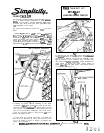
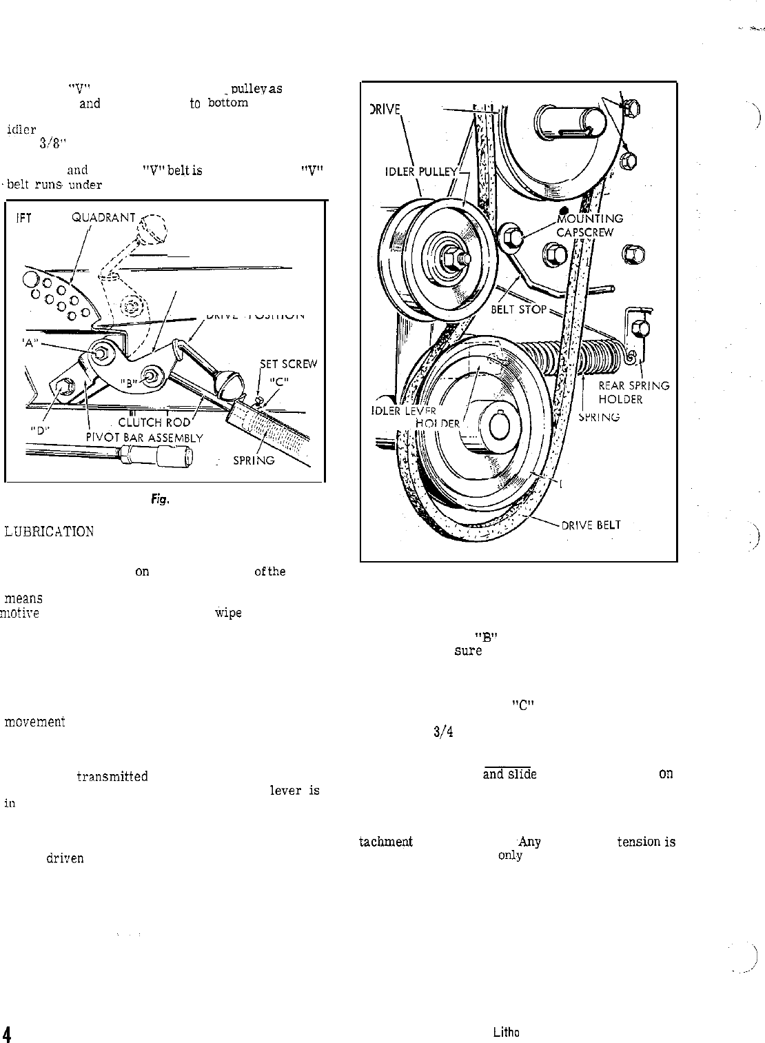
5. Mount “V” belt in place on driven
pulleyas
shown
in figure 5 and attach spring
to
b&am
hole in the
spring holder and hook other end of the spring to the
idler
lever spring holder. Mount belt stop as shown
with
3/S”
bolt, flat washer, lockwasher and hex nut.
When idler pulley is engaged, l/S” clearance between
belt stop nud back of
“V”beltis
required. Note: “V”
‘belt
ru”s
uode,r idler pulley. See figure 5.
IFT LEVER QU,?DRANT
q‘\
/\~\
’
/
.,,,j&
“RELEASE” POSITION
CLUTCH LEVER ASSEMBLY
“DRIVE”, POSITION
F;s.
4
LUURICATION
The power take-off is lubricated by means of one
grease fitting located
on the bottomfront
ofthe
drive
‘bracket assembly. Occasionally apply grease by
means
of a standard grease gun loaded with auto-
motive
type grease. Be sure to wipe dirt and grit
from grease fitting before applying grease gun. Lu-
bricate all pivot points and idler pulley bearings with
SAE 20 oil every few hours of operation.
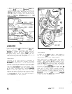
OPERATION
Operation of the power take-off is controlled by
m”veme”t
of the clutch lever assembly. See figure
4. When the clutch lever is in the forward raised
position, the clutch rod releases the tension holding
the idler pulley against the drive belt, and power
will not be
transmitted
to the driven pulley of the
power take-off assembly. when the clutch
lever
iS
ia
the back, depressedposition, theclutchrodapplies
tension to the idler pulley and as the idler pulley
takes-up the slack in the drive belt, power is trans-
mitted from the drive pulley on bevel gear box shaft
to the
drive”
pulley of the power take-off. Figure 4
shows clutch lever in drive position.
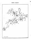
BELT GUARD SUPPORT MTG. BOLTS
I
IRIVE
PULLEY
SPRING
K
DRIVEN PULLEY
Fig. 5
ADJUSTMENT
At points “A” and “B” of figure 4, check tightness of
hex nut to be
sure
that clutch lever assembly and
clutch rod are free to pivot without binding.
Place clutch lever in “drive” position and observe
clearance between collar
“C” (figure 4) and end of
bracket. This clearance should normally be ap-
proximately
3/4
inch; at this setting the idler pulley
should be snugly against the drive belt. If additional
tension is required, release clutch lever and loosen
set screw on collar
andslide
collar farther back on
clutch rod. Retighten set screw in collar and put
clutch lever in drive position. Recheck clearance.
The tension of the idler pulley against the drive belt
must be sufficient to operate whichever tractor at-
tachme@
is being used. ,Any additional
tension
iS
unnecessary and will
only cause premature failure
of belts and idler pulley bearings.
4
Litho in USA
Form MF-49