8
POWER STAKE-OFF
For operation of Rotary Mower and Sickle Bar attach-
+nts,
a power take-off attachment is required. This
consists of the power take-off assembly,
“V”
pulley
for bevel gear shaft, drive belt, belt guard, and belt
SLOP
packaged in one carton.
For ease of attachment follow the step; outlined
below.
1. Mount
“V”
pulley to
shaft
of bevel
gear
assemble
(
see figure 1
)
and secure in place with key and
set
screw.
Hub of
“V”
pulley is
to
face inward.
Place
drive belt on
“V”
pulley and mount belt
guard
support
to.:
inside surface of side plate nearest drive pulley. See‘
figure
5
for mounting bolt location.
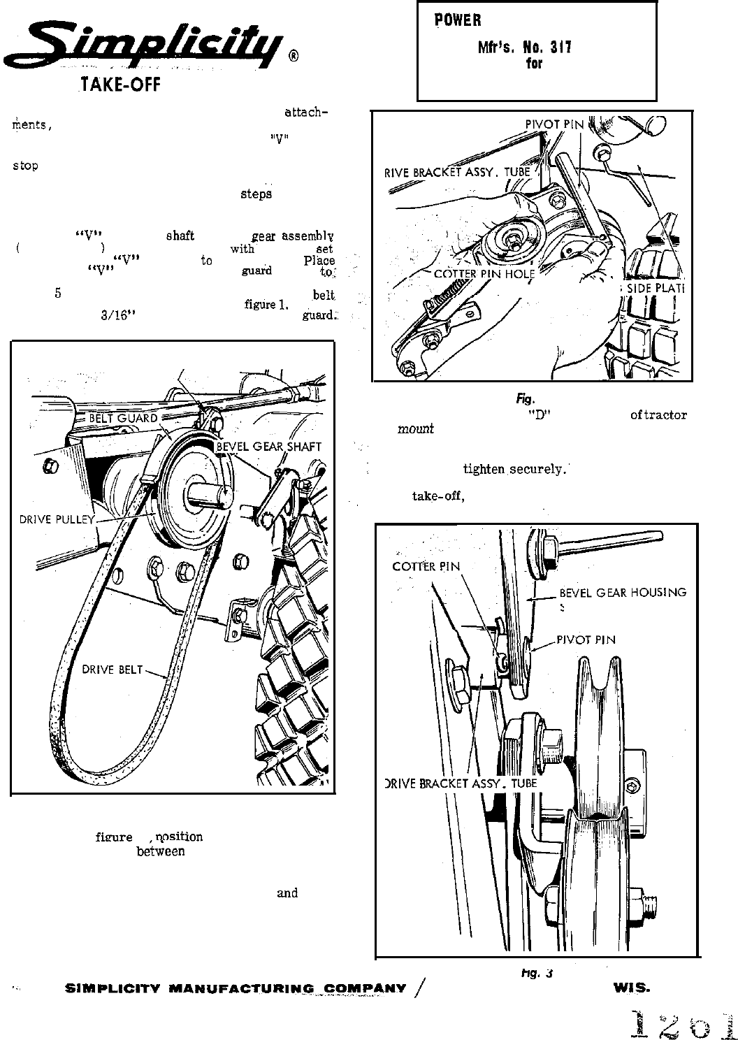
Attach the
~belt.
guard to the guard support as shown in
figure
1.
Allow
approximately
3/16”
clearance between belt and hard;:
BELT GUARD SUPPORT
Fig. I
2. Holding the power take-off assembly in left hand
as shown in
fieure 2. oosition the tube of the drive
bracket assembly
b&&n
the bevel gear housing
side plates. Align the holes in side plates with the
hole in drive bracket assembly tube and insert
pivot pin through holes in side plates
and
drive
bracket assembly tube.
3. Push pivot pin through the holes in bracket and
tube until the position of cotter pin hole in pivot
pin is as shown in figure 3. Secure in position with
POWER
TAKE-OFF KIT
Mfr’s.
NO.
311
for
LANDLORD RIDING TRACTOR
BEVEL GEAR HOUSING SIDE PlqT’
r
\
.;;I-’
63. 2
4. Remove hex cap screw
“D”
from frame
oftractor
and
mount
bracket in place under lift lever quadrant.
See figure 4. Position the pivot bar assembly flush
against bottom of lift quadrant and re-install hex
cap screw and
tighten,securely.’
Check alignment of
drive pulley on bevel gear shaft, driven pulley of
power takg-off, and idler pulley, and adjust driving
pulley if necessary.
~,
SIDE PLATE
3RIVE
B
cotter pin furnished.
mg.
J
..,
SIMPIJCITV
MARUFACTURIW-G,,.CO,~-~,ANV
/
PORT WASHINGTON.
WIG.


