


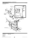
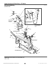

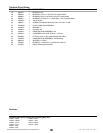
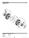
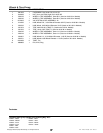
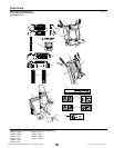
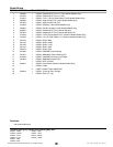
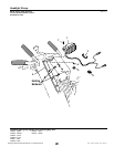
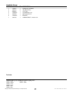

Traction Drive Group
NOTE: Unless noted otherwise,
use the standard hardware torque
specification chart.
Mounted inside of frame.
Mounted outside
of frame.
Grease I.D. teeth•
and flange.
Be sure tie bar support is in place. Move axle to
left (as viewed from back) to take up end play.
Move set collar (Ref. 49) to right to remove end
play in pivot arm (Ref. 40). Torque set screw
(Ref. 43) to 10 - 14 ft-lbs.
Apply grease to
bearing areas.
Mounted
outside of
frame.
Must pivot
freely.
Mount in
hole at
upper rear
corner of
frame.
Torque to•
18 - 21 ft-lbs.
Assemble Ref. 40, 44 & 51
with no end play. Parts
must rotate freely.
Grease bearing
area of Ref. 57.
Apply anti-seize
compound to wheel hub
area of Ref. 49 & 57.
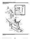
Mount to bracket in
frame weldment.
Mounted outside
of frame.
Apply Loctite and•
Torque to 55 - 60
in-lbs. when all parts
are against hub.
Torque to
10 - 14 ft-lbs.
Pack groove
with grease.
Hook end to
top left corner
slot of frame.
Lubricate with
5W 50 Synthetic oil.
Apply loctite
(2 places).
1
2
3
4
5
6
7
9
10
11
12
13
14
15
16
17
18
1
20
21
22
23
24
25
26
27
28
29
31
32
48
49
46
44
51
50
45
26
42
41
52
53
1
20
2
3
3
2
19
60
1
47
46
33
26
57
56
38
39
40
55
58
59
50
33
39
34
36
35
37
54
15
8
30
8
2
3
43
987054
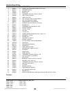
The above parts group applies to the following Mfg. Nos.:
2005
34
© Copyright Simplicity Manufacturing, Inc. All Rights Reserved.
1694847 - 10560E
1694848 - 10560EX
1694849 - 11570E
1694850 - E11570
1694851 - 1380E
1694852 - E1380
1694867 - 9560E
1694872 - 1390E
1694914 - 9560EX
1694915 - 1390EX
TP 400-4250-00-LW-S