


16
Initial Installation
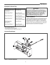
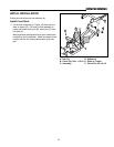
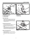
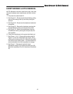
Figure 16. Install Drive Shaft
A. Key
B. 1/4-20 Centerlock Nut
C. Set Screw
D. 1/4-20 x 1-7/8 Capscrew
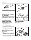
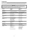
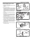
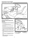
Figure 18. Cable and Wire Routing
Secure Cables
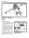
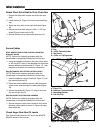
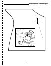
DRILL REMOTE DEFLECTOR CONTROL MOUNTING
BRACKET HOLES
NOTE: Perform the following procedure after the
snowthrower is completely installed for the first time.
1. Using the template included in the back of this manu-
al, drill two 9/32” holes in the dashboard to mount the
remote deflector control bracket (C, Figure 17). See
template at the back of this book for instructions.
SECURE REMOTE DEFLECTOR CONTROL CABLE
NOTE: Perform the following procedure after the
snowthrower is completely installed for the first time.
1. Insert the deflector control handle (B, Figure 17) into
the mounting bracket (C).
2. Route the remote deflector control cable and spout
rotator motor wires through the cable guide (Figure
18).
3. Secure the handle (B, Figure 17) using a clevis pin
(A) and hair pin clip (D).
A
B
C
D
Attach Short Drive Shaft to Drive Chain Box
1. Grease the drive shaft coupler and chain box input
shaft.
2. Install the key (A, Figure 16) into the input shaft key-
way.
3. Attach the drive shaft to the input shaft (see Figure
16).
4. Secure the drive shaft using a 1/4-20 x 1-7/8” cap-
screw (D) and center-lock nut (B).
5. Secure the key with an hex socket set screw (C).
Figure 17. Install Remote Deflector Control
A. Clevis Pin
B. Deflector Control Handle
C. Mounting Bracket
D. Hair Pin Clip
A
B
C
D
SECURE SPOUT ROTATOR WIRE HARNESS
NOTE: Perform the following procedure after the
snowthrower is completely installed for the first time.
1. Secure the spout rotator wire harness to the remote
deflector control cable as shown in Figure 18 using
three cable ties.
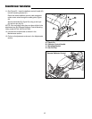
Check Auger Gear Box Oil Levels
See “Check Auger Gear Box Oil” and in the MAINTE-
NANCE section of this manual.