


26
Service
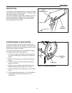
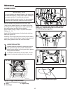
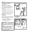
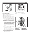
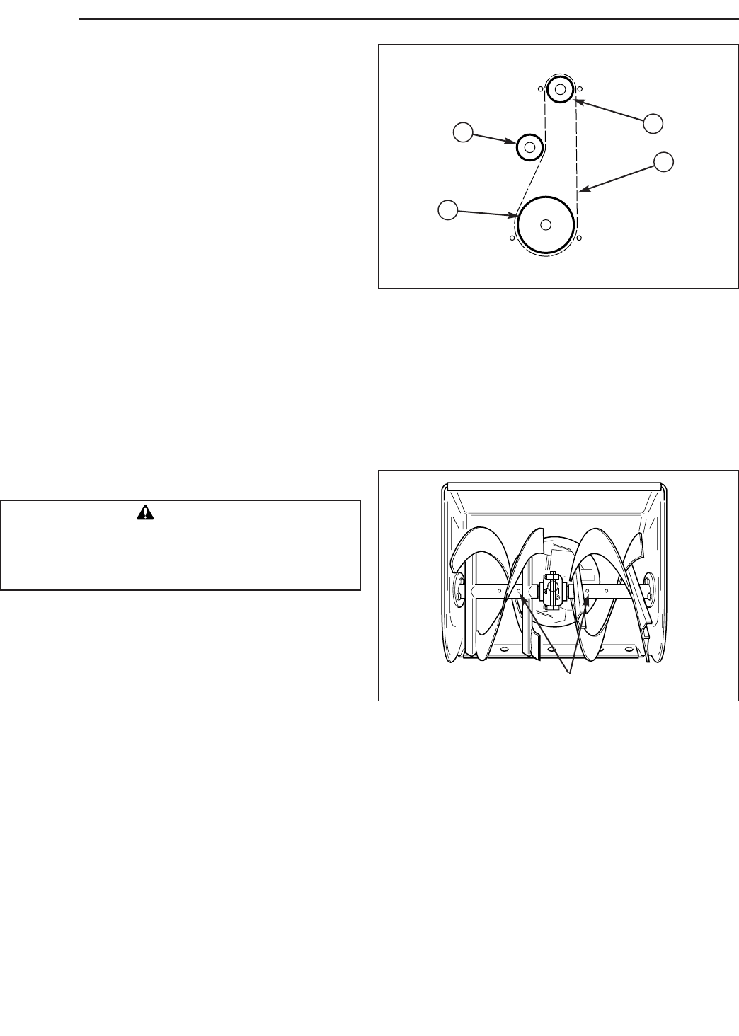
Figure 26. Belt Pattern (as viewed from front of
snowthrower)
A. Engine Pulley C. Idler Pulley
B. Drive Belt D. Driven Pulley
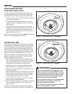
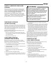
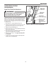
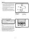
Figure 27. Shear Pins
SHEAR PIN REPLACEMENT
Under most circumstances, if the auger strikes an object
which could cause damage to the unit, the shear pin will
break. This protects the gear box and other parts from
damage.
The shear pins are located on the auger shaft as shown
in Figure 27. To replace the shear pins, tap out broken
pin with a pin punch, and install a new shear pin and cot-
ter pin. Spread the legs of the new cotter pin fully. Do
NOT replace shear pins with anything other than the
correct grade replacement shear pin. See the
REPLACEMENT PARTS section at the back of this man-
ual for the correct part numbers. (Use of bolts, screws or
a harder shear pin will lead to damaged equipment.)
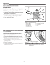
Belt Stops
Belt Stops (Auger Pulley Only)
B
C
A
D
Shear Pins
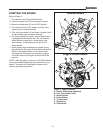
6. Reverse the procedure to install the belts. Be sure
there are no twists and the belts are properly seated
in the grooves. Adjust the belt stops so there is 1/8”
(3mm) clearance between belt and stop. The pattern
for both belts is shown in Figure 26.
7. Check the traction drive tension and auger drive ten-
sion. Follow the procedures under AUGER DRIVE
BELT ADJUSTMENT.
8. Make sure the auger stops when the auger drive
lever is released. Make sure traction drive stops
when the traction drive lever is released. If not, check
the drive tension. If a problem exists, see your dealer.
WARNING
Do not go near the discharge chute or auger when the
engine is running. Do not run the engine with any
cover or guard removed.