


16
MOWER DECK REMOVAL &
INSTALLATION
NOTE: Perform mower removal and installation on a
hard, level surface such as a concrete floor.
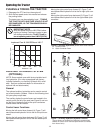
Removing the Mower Deck
1. Start the engine
2. Set the mower cutting height to minimum.
3. Fully raise the attachment lift.
4. Stop the engine.
48” AND 60” MOWERS
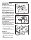
5. Pivot the two front gauge wheels from mowing posi-
tion to sliding position by pushing down on the top of
the spindle and pivoting the wheel (see Figure 12).
54” MOWERS
5. Remove the hair pin clip, push down on the top of the
spindle, and rotate the gauge wheel into sliding posi-
tion (see Figure 12). Replace the hair pin clip.
ALL MODELS
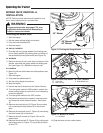
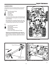
6. Move the left rear slide wheel into slide position (see
Figure 13).
7. Start the engine.
8. Fully lower the attachment lift.
9. Set the cutting height to maximum.
10. Stop the engine.
11. Unhook the two lift chains from the tractor lift arms.
12. Turn the ignition switch to RUN position, and set the
mower cutting height to minimum (it is not necessary
to start the engine).
13. Turn the ignition switch to the OFF position.
14. Disconnect the electrical connection from the tractor
and recap the tractor electrical socket. See Figure
15.
15. Remove the long hitch pin (B, Figure 16) and safety
clip connecting the hitch bucket (A) to the mower
deck.
16. Remove the two small pins (C, Figure 16) connecting
the hitch bucket (A) to the tractor.
17. Remove the hitch bucket (A, Figure 16) from the
mower deck.
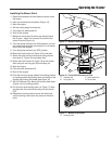
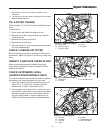
18. Remove the drive shaft (D, Figure 16) by pulling back
the locking collar (A, Figure 17) and pulling the shaft
off the PTO.
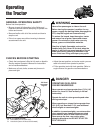
Operating the Tractor
WARNING
Engage parking brake, disengage PTO, stop
engine and remove key before attempting to
install or remove the mower.
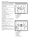
Figure 12. Pivoting the Gauge Wheels
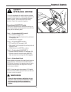
Figure 13. Rear Slide Wheel - 48” & 60” Mowers
A. Clevis Pin C. Slide Wheel Arm
B. Hair Pin Clip
Figure 14. Mower Lift Chains
A. Lift Chains
A
C
B
A
19. Slide the deck out from under tractor.
54” Mower
48” Mower &
60” Mower