Belt Replacement
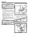
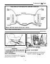
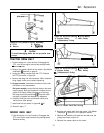
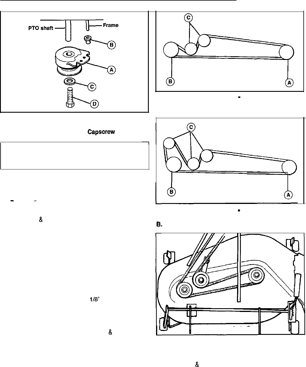
Figure 29. Drive Belt Routing
-
Hydro Models
A. Engine Pulley C. Idler Pulley
B. Transmission Pulley
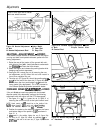
Figure 28. PTO (Electric Clutch) Assembly
A. PTO C. Washer
B. Sleeve D.
Capscrew
A
CAUTION
To avoid damaging belts, do not pry belts over
pulleys.
TRACTOR DRNE BELT
1. Park the tractor on a level surface. Disengage the
PTO, turn off the engine and set the parking brake.
-
~.
Remove tne key.
2. Remove the mower deck from the tractor. See Mower
Installation
&
Removal on page 8.
3. Unplug the wiring harness from the PTO. Remove
the PTO as shown in figure 28.
4. Remove the drag link rear hardware. When reassem-
bling, apply Loctite to nut before tightening.
5. On gear models, disconnect the wires from the neu-
tral switch on the transmission.
On hydro models, loosen the belt stop on the trans-
mission pulley. Belt stop hardware is located on the
inside of RH frame. Move belt stop out of the way.
Belt stop should be positioned
I/8” from belt when
new belt is installed and hardware is tightened.
6. Carefully slide belt over transmission pulley and
remove from other pulleys.
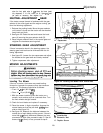
7. Install new belt as shown in figures49
&
30.
8. Reverse steps i-7..
Figure 30. Drive Belt Routing
-
Gear Model
A. Engine Pulley C. Idler Pulley
B.
Transmissioin Pulley
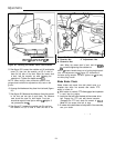
Figure 31. Mower Deck Belt Routing
MOWER DECK BELT
1. Park the tractor on a level surface. Disengage the
PTO, turn off the engine and set the parking brake.
Remove the key.
2. Remove the mower deck from the tractor. See Mower
Installation
&
Removal in the Operation section.
3. Remove the old belt and install the new belt over the
pulleys as shown in figure 31.
4. Reinstall the mower deck on the tractor.
25


