Controls
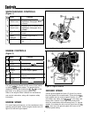
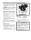
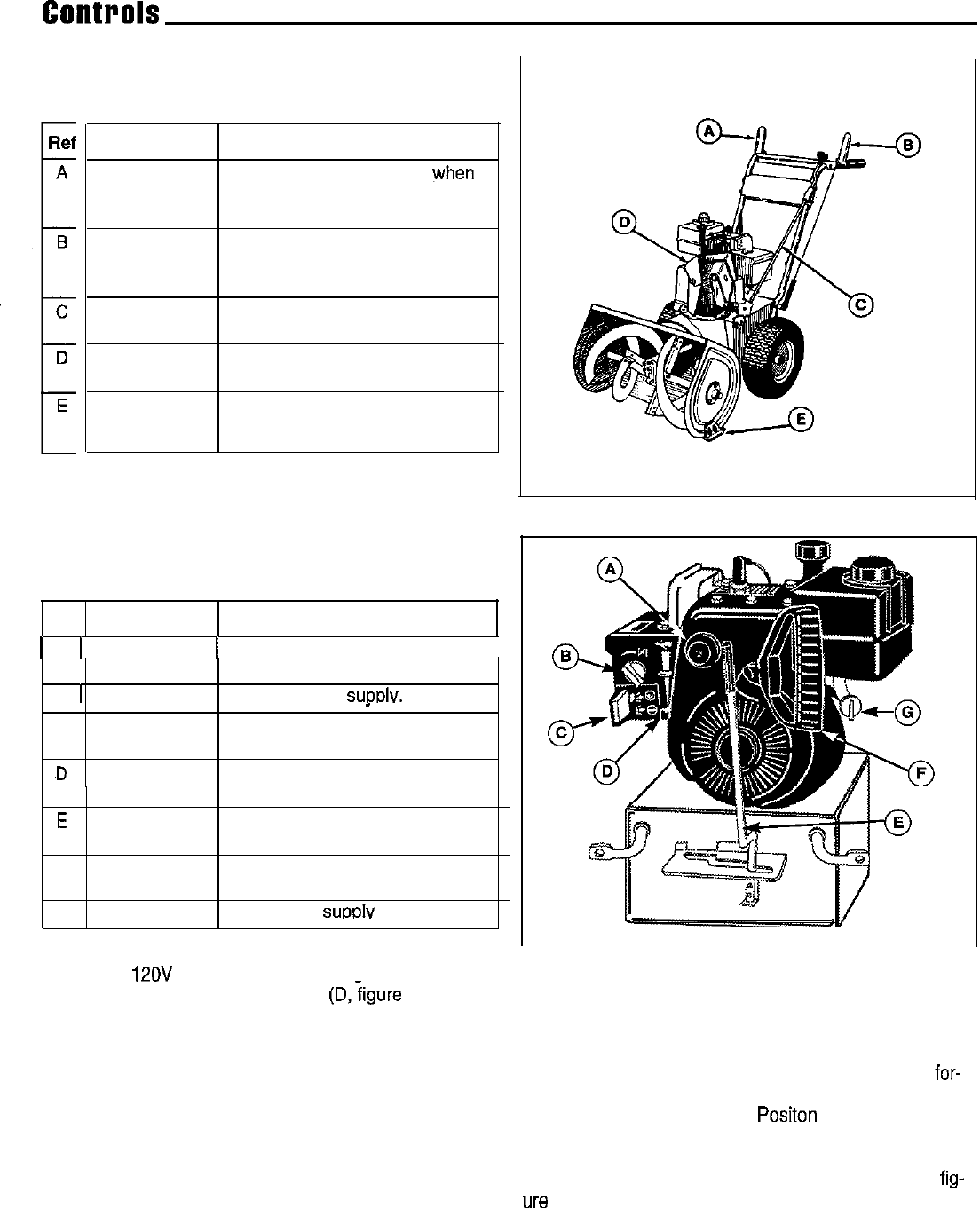
SNOWTHROWER CONTROLS
(Figure 1)
Ref
A
B
i
C
D
E
Name
Auger Control
Clutch Lever
Drive Control
Clutch Lever
Chute Control
Rod
Chute
Deflector
Skid Shoes
Function
Engages auger/impeller when
depressed; disengages when
released.
Engages drive
to
wheels when
depressed; disengages when
released.
Controls direction snow is
thrown.
Controls angle snow is
thrown.
Controls height of scraper
bar.
Figure 1. Snowthrower Controls
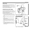
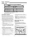
ENGINE CONTROLS
(Figure 2)
Ref Name
Function
1 A 1 Primer
1 Primes the carburetor.
I
Button
B 1 Choke
C Ignition
Switch
,D
Throttle
Enriches fuel sutmlv.
_
Allows starting and stopping
of the engine.
Controls engine
speed.
Lever
E
Shift Lever
F Starter
Handle
G Fuel Valve
Controls ground speed and
direction.
Used to start engine.
Turns fuel
SUDDEN
on or off.
The engine can be started with the rewind (rope) starter
I
or optional
12OV
electric starter. The engine can be
Figure 2. Engine Controls
stopped by moving the throttle lever (D,figure 2) all the
way down, or by pulling out on the ignition key.
GROUND SPEED
Refer to the engine Owner’s Manual for maintenance
and service instructions, along with important safety
Use the ground speed shift lever (E, figure 2) to control
information.
the drive speed of the snowthrower. There are three
for-
ward speeds and one reverse speed. Position 1 is for
extra deep, wet, heavy snow. Positon 2 is for deep, wet,
ENGINE SPEED
heavy snow. Position 3 is for light, fluffy snow and to
drive the snowthrower without blowing snow. To change
For overall best performance, run the snowthrower at full
speeds, first release the drive control clutch lever (B,
fig-
operating engine speed. Use the engine throttle lever (D,
ure
I), then move the ground speed shift lever to the
figure 2) to set the engine speed.
desired speed setting.
4


