


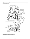
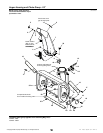
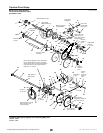

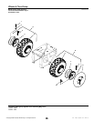

Traction Drive Group
NOTE: Unless noted otherwise,
use the standard hardware torque
specification chart.
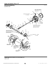
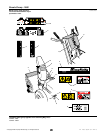
Mounted inside of frame.
Mounted outside
of frame.
Grease I.D. teeth•
and flange.
Be sure tie bar support is in place. Move axle to
left (as viewed from back) to take up end play.
Move set collar (Ref. 51) to right to remove end
play in pivot arm (Ref. 42). Torque set screw
(Ref. 45) to 10 - 14 ft-lbs.
Apply grease to
bearing areas.
Mounted
outside of
frame.
Must pivot
freely.
Mount in
hole at
upper rear
corner of
frame.
Torque to•
18 - 21 ft-lbs.
Assemble Ref. 42, 44 & 49
with no end play. Parts
must rotate freely.
Grease bearing
area of Ref. 62.
Apply anti-seize
compound to wheel hub
area of Ref. 40 & 62.
Mount to bracket in
frame weldment.
Mounted
outside of
frame.
Apply Loctite and•
Torque to 55 - 60
in-lbs. when all parts
are against hub.
Torque to
10 - 14 ft-lbs.
Apply locktite,
torque to
8 - 10 ft-lbs.
Pack groove
with grease.
Hook end to
top left corner
slot of frame.
Lubricate with
5W 50 Synthetic oil.
Apply loctite
(2 places).
1
2
3
4
5
6
7
8
9
10
11
12
13
14
15
16
17
18
19
20
21
3
23
25
26
27
28
29
30
31
32
33
34
35
36
37
38
39
40
41
42
44
45
46
47
48
49
50
51
26
27
4
5
5
4
2
22
1
43
41
55
33
62
63
54
53
52
61
64
65
45
55
53
56
57
58
59
60
17
2
3
66
3
2
4
24
5
67
SC985638
The above parts group applies to the following Mfg. Nos.:
2003
22
© Copyright Simplicity Manufacturing, Inc. All Rights Reserved.
1694436 - 1060M
1694440 - 1060E
TP 400-3891-01-LW-S