


SIGMA ELECTRONICS, INC.
BSG-26 SERIES
SERVICE MANUAL
CAUTION
These servicing instructions are for use by qualified personnel only. To reduce the risk of
electric shock do not perform any servicing other than that contained in the operating instructions
unless you are qualified to do so. Refer all servicing to qualified service personnel.
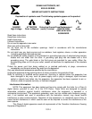
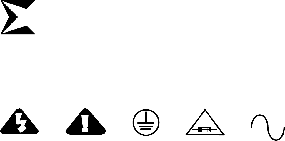
Explanation of symbols used. The following symbols appear on the product.
DANGER ATTENTION Protective Ground Fuse Replacement AC
High Voltage Refer to Manual (earth) Terminal RISK OF FIRE REPLACE Power
FUSE AS MARKED
Read the IMPORTANT SAFETY INSTRUCTIONS before installing or operating this equipment. Keep this
information in an accessible location for reference by all users. Follow all instructions in this manual for safe operation.
JUMPERS:
The following jumpers are located on the PCB inside the enclosure. They are provided for custom
configuration of the BSG-26N and BSG-26P. The modules should not require any adjustments for normal Black Signal
operation.
J1 Superblack/Black Select, Default position, Pins 2-3 (Black), Optional position, Pins 1-2 (Superblack).
J2 Setup On/Off, Default position 1-2 (Setup On, NTSC, BSG-26N), Position 2-3 (Setup Off, PAL, BSG-26P)
J3 Subcarrier Phase Select, 0° or 180°, Default position is 0°, Opposite position is 180°
ADJUSTMENTS:
The following adjustments are located on the PCB inside the enclosure. They are provided for custom
configuration of the BSG-26N and BSG-26P. The modules should not require any adjustments for normal Black Signal
operation.
C31 Subcarrier center frequency.
R7 Sync./Setup Gain, Set per standards specified.
R14 Subcarrier Null, Minimizes residual subcarrier on output signal.
R20 Burst Gain, Set per standards specified.
R22 Variable Subcarrier Phase Adjust, 180° SCH Phase adjust, See “JUMPER” section, jumper 3 options.
R25 Subcarrier Symmetry, Provides minimum difference in duty cycle between 0° and 180° setting of J3
DISASSEMBLY:
NOTE: REMOVE THE POWER BEFORE DISASSEMBLY OF THE UNIT.
Disassembly is not necessary for normal Black Signal operation.
Tools needed: #1 Phillips head screw driver.
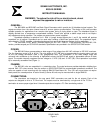
Procedure: 1st, remove the four rear panel Phillips head machine screws, one per corner. 2nd, remove the
electrical assembly by pulling the rear panel from the enclosure; the PCB is attached to the rear panel.
TECHNICAL MANUAL:
A manual including schematics, circuit description, parts list and setup guide is available upon request. This
information is intended for the service of the unit. The units should be serviced by qualified personnel only. Sigma
Electronics, Inc. recommends service to be performed by the Factory Service Center.
4 OF 4