


18
Maintenance (continued)
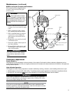
Cutting performance of your machine
depends a great deal on proper cutter
blade adjustment. Properly adjusted
blades will oscillate freely yet help pre-
vent binding of cut material between
blades. Adjust blades as follows:
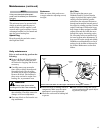
Loosen all blade locknuts at least 1.
one full turn.
Tighten each blade shoulder bolt 2.
firmly, and then loosen the shoulder
bolts 1/4 to 1/2 turn.
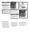
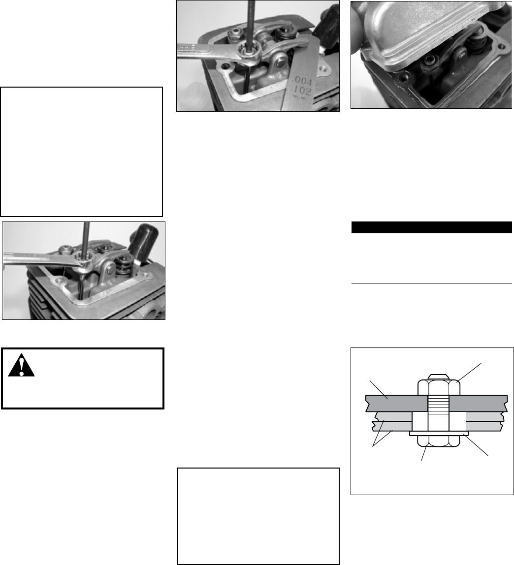
Locknut
Guide Bar
Cutter
Blades
Shoulder Bolt
Washer (should
turn freely)
Adjusting cutter blades
Cutter blade adjustment
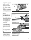
Working from the gearcase end, lock 3.
each bolt in place by firmly tighten-
ing its locknut while preventing the
shoulder bolt from turning.
When shoulder bolt adjustment is 4.
correct, there should be a gap of
0.25–0.50 mm between the cutter
blades and the flat washers, and the
flat washer beneath each bolt head
should turn freely.
WARNING!
The cutter blades are very
sharp! Always wear gloves when
working around the cutter assembly.
CAUTION!
Operating the trimmer with worn
or improperly adjusted cutters will
reduce cutter performance and may
also damage your machine. Never
operate the machine with damaged
or worn cutters.
IMPORTANT!
If a new gasket is not available and/
or the old gasket is not damaged, the
old gasket may be reused. Never use
cracked or damaged gaskets!
Turn engine over several times, 6.
and return to TDC-compression.
Recheck with proper feeler gauge to
make sure clearance adjustment did
not change as a result of tightening
the locknut. Readjust as necessary.
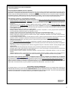
Replace rocker arm cover gasket 7.
to assure proper sealing and install
cover.
135-Hour Maintenance
Combustion chamber should be ■
decarbonized, and the valve clear-
ance should be adjusted. It is highly
recommended that this is done
by a Shindaiwa-trained service
technician.
Replace the spark plug annually: Use
■
only the type recommended in the
”Specifications” section or an equiva-
lent resistor type spark plug of the
correct heat range. Set spark plug
electrode gap to 0.6 mm.
Remove cylinder cover, rocker arm 1.
cover, and spark plug.
Rotate the
crankshaft while observing the pis-
ton through the spark plug opening.
When the piston is at the top of the
compression stroke (TDC), the valves
can be adjusted.
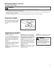
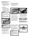
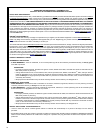
Loosen adjuster locknut so that the 2.
2.5 mm Allen socket head adjust-
ment screw can turn freely.
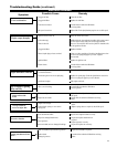
Insert 0.10 mm feeler gauge between 3.
valve stem tip and rocker arm.
Turn adjustment screw (clockwise = 4.
tighter, counter-clockwise = looser)
until feeler gauge is almost snug.
Back off just enough to allow gauge
to slip out with limited resistance.
While holding the adjustment 5.
screw in place with the Allen driver,
tighten the locknut with a wrench.
CAUTION!
Performing a valve adjustment
■
incorrectly may cause hard
starting and/or can damage the
engine.
If you are unfamiliar with this
■
engine or uncomfortable with
this procedure, consult with an
authorized Shindaiwa servicing
dealer.
Valve Adjustment