


7
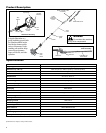
An Emission Control Label is located on the unit. (This is an EXAMPLE ONLY; information on label varies by en-
gine FAMILY).
PRODUCT EMISSION DURABILITY (EMISSION COMPLIANCE PERIOD)
The 300 hour emission compliance period is the time span selected by the manufacturer certifying the engine
emissions output meets applicable emissions regulations, provided that approved maintenance procedures are
followed as listed in the Maintenance Section of this manual.
Emission Control (Exhaust & Evaporative)
EPA 2010 and Later and/or C.A.R.B. TIER III
The emission control system for the engine is EM/TWC (Engine Modication and 3-way Catalyst) and for the fuel tank
the Control System is EVAP (Evaporative Emissions) or N (for nylon tank). Evaporative emission may be applicable to
California models only.
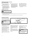
Assembly
Before assembling, make sure you
have all the components required for a
complete unit:
Hedge Trimmer Assembly
■
Prior To Assembly
Kit with this manual and tool kit for ■
routine maintenance.
Cutter blade cover
■
Carefully inspect all components for
damage.
IMPORTANT!
The terms “left”, “left-hand”, and
“LH”; “right”, “right-hand”, and “RH”;
“front” and “rear” refer to directions as
viewed by the operator during normal
operation.
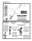
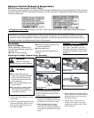
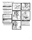
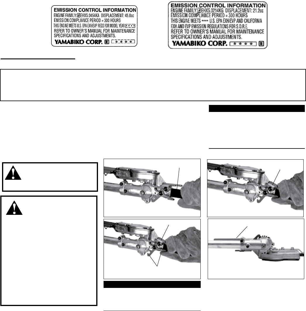
Adjusting the Hedge Trimmer Cutter Assembly
WARNING!
WARNING!
Never run the engine
when adjusting the cutter assembly.
Latch Release
Grasp the outer tube near the handle
Adjustment Lever
Adjustment Lever
Pivot the cutter assembly using the
adjustment lever...
Press the latch lock
Make sure the latch lock and the latch release
return securely to the locked position
Latch Lock
Latch Lock
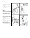
The cutter blades are very ■
sharp. Do not grasp the blades
with your hands. Always use
gloves when working near the
cutter assembly.
Do not allow the blades to con-
■
tact your body.
Do not touch the cutter blades
■
when the engine is running.
The blades can oscillate even
if the engine is idling.
Position the hedge trimmer on a flat, 1.
level surface.
With your right hand, grasp the outer 2.
tube near the handle. With your left
hand, grip the adjustment lever on
the cutter assembly.
IMPORTANT!
The latch lock provides an interlock to
help prevent inadvertent depression of
the latch release.
With the index finger of your left 3.
hand, press the latch lock. With your
left thumb, press the latch release.
While holding the latch release 4.
down, pivot the cutter assembly
away from you using the adjustment
lever until it is at the desired cutting
angle.
Release the latch lock and the latch 5.
release. Make sure the latch lock and
the latch release return securely to
the locked position.
Remove the cover from the cut-6.
ter blade. The engine now may be
started (refer to the section ”Start-
ing the Engine”.)