


Recommended
Strap and
Hanger
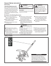
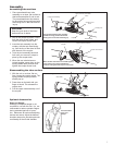
When the two tube halves are locked together,
press down on the spring-loaded latch
protector and tighten the coupler screw knob.
7
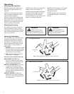
Assembly
Press latch
With the unit on a clean, at sur-1.
face, loosen the coupler screw. The
spring-loaded coupler protector
should pop up.
Press down on the latch with your 2.
nger or thumb. This releases the
coupler lock.
Pull the upper tube assembly out of 3.
the coupler.
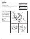
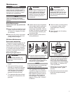
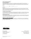
Disassembling the tube sections
Tool assembly
Lower tube assembly
Coupler
Latch
Coupler screw
knob
Locking hole
Latch protector (extended)
Slip off the protective plastic covers 2.
from the ends of both tubes, and
loosen the coupler screw knob.
Insert the tool assembly into the 3.
coupler, with the tool decal facing
up, until the line of the decal is ush
with the end of the coupler.
Twist the tool assembly back and 4.
forth until you are sure it snaps in
place by the coupler latch.
When the two tube halves are 5.
locked together, press down on the
spring-loaded latch protector and
tighten the coupler screw knob.
Latch Protector (lowered)
Coupler Screw Knob
Coupler
Assembling tube sections
Place powerhead/lower tube 1.
assembly on a clean, at surface so
that both assemblies t end to end.
The powerhead/lower tube assem-
bly should be facing positioned with
the locking hole in the tube end fac-
ing up.
CAUTION!
Keep the open ends of the tubes
clean and free of debris!
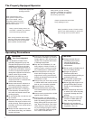
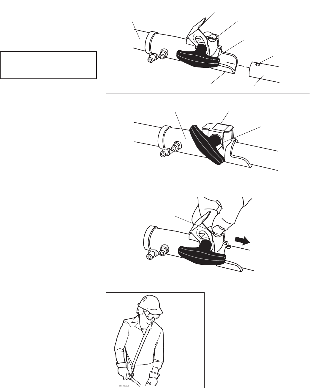
Strap and Hanger
Although a strap and hanger is not
required for use with this unit, it is rec-
ommended to reduce operator fatigue
during extended periods of opera-
tion.
Make sure all hooks and adjusting
devices are secure. Adjust the harness
shoulder strap so the shoulder pad rests
comfortably on the off-side shoulder.
Optional Accessories
Assembling tube sections
The powerhead/lower tube assembly
should be facing positioned with the
locking hole in the tube end facing up
Disassembling the tube sections