6
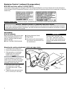
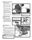
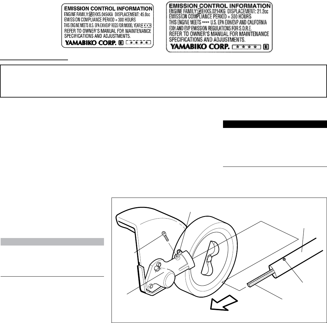
Emission Control Label (located on Engine) (EXAMPLE ONLY, information on label varies by FAMILY).
PRODUCT EMISSION DURABILITY (EMISSION COMPLIANCE PERIOD)
The 300 hour emission compliance period is the time span selected by the manufacturer certifying the engine emissions
output meets applicable emissions regulations, provided that approved maintenance procedures are followed as listed in
the Maintenance Section of this manual.
Emission Control (exhaust & evaporative)
EPA 2010 and Later and/or C.A.R.B. TIER III
The emission control system for the engine is EM/TWC (Engine Modication and 3-way Catalyst) and for the fuel tank the
Control System is EVAP (Evaporative Emissions) or N (for nylon tank). Evaporative emission may be applicable to California
models only.
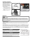
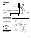
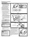
Gearcase
Flex drive cable
Shaft tube
Gearcase
clamp screw
Gearcase
index
screw
Mounting the cutting attachment shield and edger blade
NOTE:
It may be necessary to pull the ex
cable out from the shaft tube, engage
into the gearcase and then slide the
assembly onto the shaft tube.
Loosen gearcase clamp screw.1.
Remove the gearcase index screw.2.
Slide gearcase on to shaft tube, 3.
engaging ex drive cable with
female socket in gearcase.
Align index screw hole in gearcase 4.
with index hole in shaft tube,
and install index screw. Tighten
securely.
Tighten the clamp bolt and torque 5.
to 5.9 - 8.0 N•m (52 - 69 in•lbs).
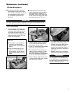
Assembly
Prior to assembly
Before assembling, make sure you have
all the components required for a com-
plete unit. Carefully inspect all compo-
nents for damage.
Outer Tube/Main Shaft Assembly ■
IMPORTANT!
The terms “left”, “left-hand”, and
“LH”; “right”, “right-hand”, and “RH”;
“front” and “rear” refer to directions as
viewed by the operator during normal
operation.
Cutting Attachment Shield
■
Edger Blade ■
Kit containing this owner's/opera- ■
tor's manual, and a tool kit for rou-
tine maintenance.
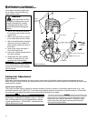
Index hole


