


5
Product Description
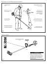
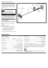
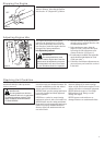
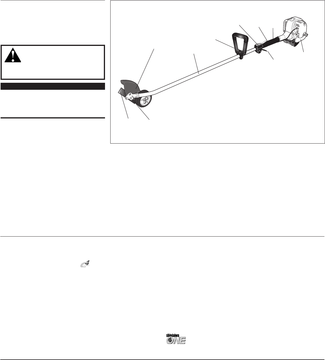
Figure 4
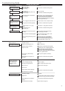
Specications
LE2510 dry weight
(Including attachments) .............................................13.4 lb./6.1 kg
Engine model .SF2510E
Engine type ................................... with Power Boost Chamber
Bore x stroke .............................................. 1.3 x 1.1 in./34 x27 mm
Displacement ....................................................... 1.5 cu. in./ 24.5 cc
Maximum power .......................................................1.1 HP/0.8 kW
@ 7500 rpm (min
-1
)
Fuel/oil ratio ..............................50:1 with ISO-L-EGD or JASO FC
class 2-cycle mixing oil*
Carburetor type ................................Walbro WYL, diaphragm-type
Fuel tank capacity ....................................................20.0 oz./590 ml
Ignition ............................................................ One-piece electronic,
program contolled
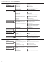
Specifications are subject to change without notice.
Spark plug ....................................................................NGK CMR5H
Air cleaner type ..................................... Non-reversible heavy-duty
filter element
Starting method .......................................................................Recoil
Stopping method ............................................................Slide switch
Transmission type .............................Automatic, centrifugal clutch
w/bevel gear
EPA Emission Compliance Period** ............................Category A
** The EPA emission compliance referred to on the emission compliance label
located on the engine, indicates the number of operating hours for which the
engine has been shown to meet Federal emission requirements. Category
C = 50 hours (Moderate), B = 125 hours (Intermediate) and A = 300 hours
(Extended).
* meets or exceeds these specifications and is recommended for
all Shindaiwa products.
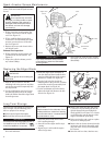
LE2510 LAWN EDGER
Outer Tube
Cutting
Attachment
Grip
Cutting
Attachment Shield
Gear case
Handle
Throttle
Trigger
Throttle
Interlock
Ignition
Switch
Fuel
Tank
IMPORTANT!
The terms “left”, “left-hand”, and “LH”;
“right”, “right-hand”, and “RH”; “front” and
“rear” refer to directions as viewed by the
operator during normal operation.
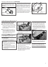
Using the accompanying illustrations as
a guide, familiarize yourself with this unit
and its various components. See Figure 4.
Understanding your unit helps ensure top
performance, long service life, and safer
operation.
WARNING!
Do not make unauthorized
modications or alterations to any of
these units or their components.
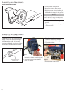
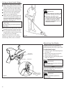
Prior to Assembly
Before assembling, make sure you have all
the components required for a complete unit:
Engine and outer tube assembly with
handle
Gearcase assembly
Kit containing this manual and tool kit
for routine maintenance. Tool kits vary
by model and may include a hex wrench,
spark plug/screwdriver combination
wrench, and spanner wrench.
Carefully inspect all components for damage.