


6
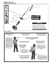
Assembly
This unit comes fully assembled. You
only need attach the accessory tool of
your choice to the powerhead. Your unit
includes:
Engine/outer tube assembly
Ŷ
Gearcase/cutter assemblyŶ
Prior To Assembly
This manual and tool kit for routine Ŷ
maintenance.
Cutter blade cover
Ŷ
Carefully inspect all components for
damage.
IMPORTANT!
The terms “left”, “left-hand”, and “LH”;
“right”, “right-hand”, and “RH”; “front” and
“rear” refer to directions as viewed by the
operator during normal operation.
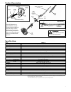
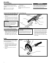
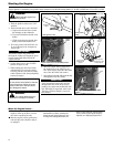
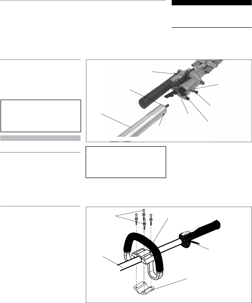
Index Screw
Gearcase/Cutter
Assembly
Mainshaft
Tube
Clamp
Outer Tube
Place the powerhead/outer tube assem-1.
bly on a clean, flat surface, spark plug
facing up.
Use the 4mm hex wrench to loosen the 2.
tube clamp and index screw. Verify that
the D-shaped shim washer is positioned
as shown.
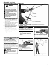
Connect the Powerhead/Outer Tube to the Gearcase
Clamp Screw
D-Washer
Index Hole
CAUTION!
Do not force the shaft tube into the
gearcase! Excessive force can dam-
age the shaft tube and mainshaft.
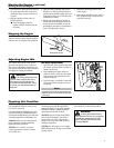
CAUTION!
Do not remove the D-shaped shim
washer! The shim washer prevents
damage from overtightening the
tube clamp screw.
Slide the outer tube into the tube clamp 3.
until the tube bottoms. If installation is
difficult, rotate the outer tube or main
shaft slightly until you feel the main-
shaft splines engage with the gearcase.
Position the outer tube so that the index 4.
hole on the outer tube is aligned with the
index screw on the gearcase tube clamp.
Using finger pressure only, thread the 5.
index screw into the index hole located
on the outer tube until it bottoms out.
Tighten the index screw and the clamp 6.
screw firmly.
NOTE:
It may be necessary to twist the outer tube
slightly for the index screw to be inserted fully.
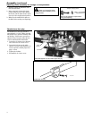
Outer Tube
Socket-head
Capscrews
Handle
Mounting Bracket
Throttle Assembly
Position the handle on the outer tube as shown
Connect the outer tube to the gearcase
Handle
This unit comes with the handle installed.
It can be re-adjusted for operator comfort
in the following manner.
Loosen the four hex screws.1.
Rotate/slide handle assembly to best 2.
position for operator comfort, usually
25 cm (10 in.) ahead of the throttle
assembly.
Tighten hex screws in a crisscross 3.
manner.