


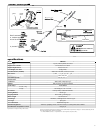
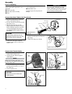
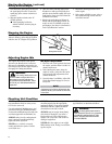
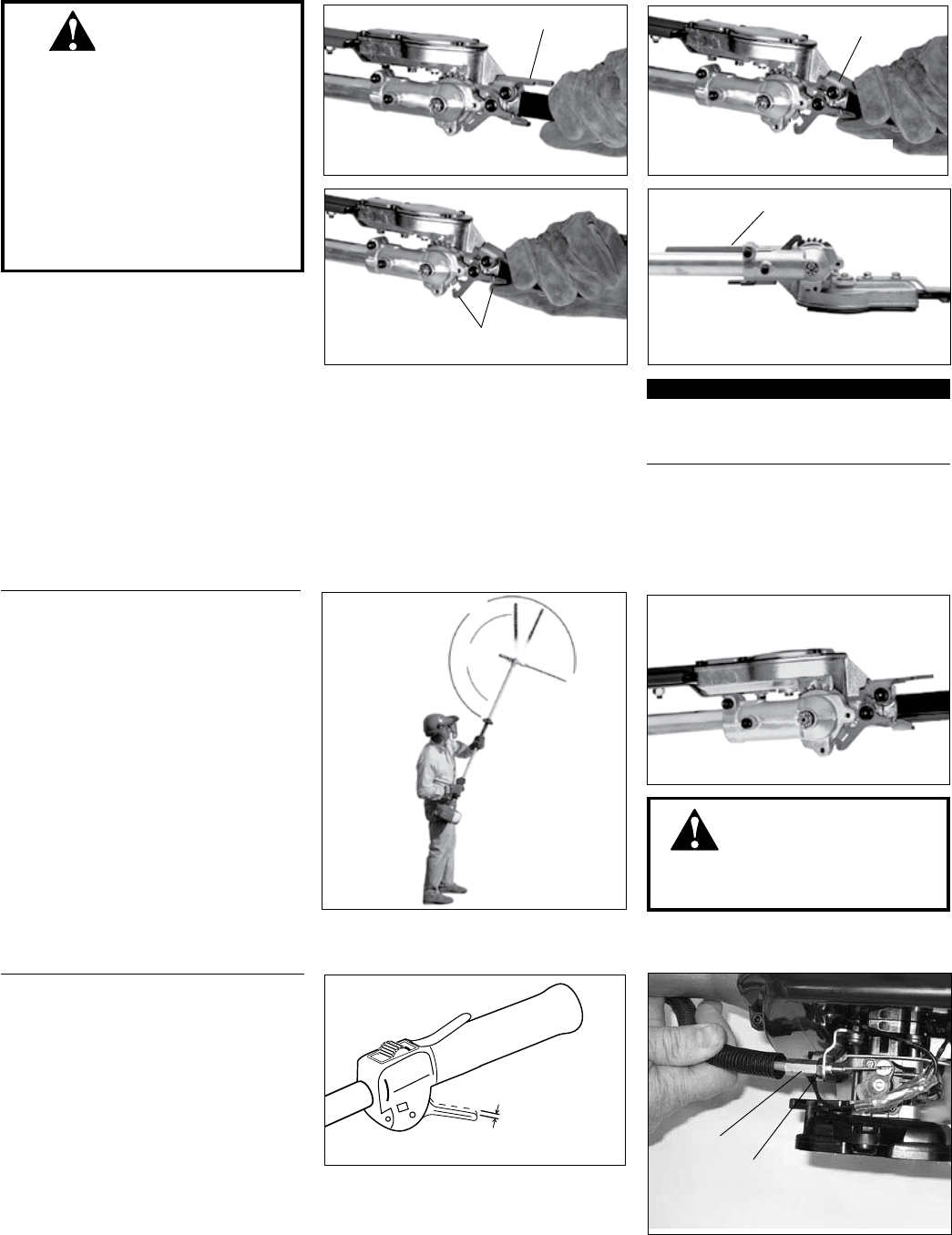
Cable
Adjuster
Rotate cable
adjuster in or
out to obtain proper free play
Lock Nut
4 - 6 mm
Throttle lever free play
7
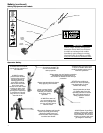
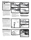
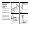
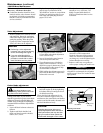
The cutter assembly can be adjusted to
eleven different positions ranging from
120° to 270° from the outer tube as shown.
Always make sure the lock latch is securely
locked after each adjustment.
Cutter Assembly Positions
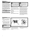
Position the hedge trimmer on a flat,1.
level surface with the engine resting
on the fuel tank guard. Make sure the
scabbard is in place on the blade.
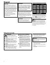
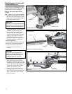
With your right hand, grasp the outer 2.
tube near the handle. With your left
hand, grip the adjustment lever on the
cutter assembly. With the index fin-
ger of your left hand, press the latch
release. With your left thumb, press the
latch lock.
270°
120°
Various blade
positions
possible
Cutter
Assembly
Positions
Adjusting the Hedge Trimmer Cutter Assembly
Assembly (continued)
The cutter blades are very sharp. Ŷ
Do not grasp the blades with your
hands. Always use gloves when
working near the cutter assembly.
Do not allow the blades to contact
Ŷ
your body.
Do not touch the cutter blades
Ŷ
when the engine is running. The
blades can oscillate even if the
engine is idling.
IMPORTANT!
The latch lock provides an interlock to
help prevent inadvertent depression of
the latch release.
WARNING!
Latch Lock
Grasp the outer tube near the handle
Adjustment Lever
Adjustment Lever
Pivot the cutter assembly using the
adjustment lever...
Press the latch lock
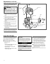
Make sure the latch lock and the latch release
return securely to the straight ahead position
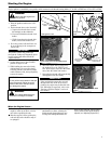
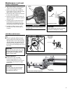
With the engine off, install the scab-1.
bard onto the blade.
Using the procedures described on the 2.
previous page, rotate the cutter assem-
bly so it is parallel to the tube. Make
sure the latch lock and the latch release
return securely to a locking position.
Make sure the scabbard is in place on the 3.
cutters before storing or transporting.
Gearcase rotated to the storage/
transportation position
Adjusting for Storage or Transportation
WARNING!
Never run the engine when
adjusting the cutter assembly to the
storage position.
Adjusting for Storage or Transportation
Latch Release
The throttle lever free play should be approxi-
mately 4 - 6 mm. Make sure that the throttle
lever operates smoothly without binding. If
it becomes necessary to adjust the lever free
play, follow the procedures and illustrations
that follow.
Loosen the air cleaner cover knob(s) and 1.
remove the air cleaner cover.
Loosen the lock nut on the cable 2.
adjuster. Turn the cable adjuster in or
out as required to obtain proper free play
4 - 6 mm.
Tighten the locknut.3.
Reinstall the air cleaner cover.4.
Throttle lever free play
While holding the latch release down, 3.
pivot the cutter assembly using the
adjustment lever until it is at the
desired cutting angle.
Release the latch lock and the latch 4.
release. Make sure the latch lock and
the latch release return securely to the
straight ahead position.
Remove the cover from the cutter blade. 5.
The engine now may be started (refer to
the section ”Starting the Engine”).