8
English
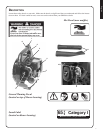
STOP SWITCH - "SLIDE SWITCH" mounted on top of handle. Push forward to start and run. Slide back to stop.
THROTTLE TRIGGER - Spring loaded to return to idle when released. During acceleration, press trigger gradually for
best operating technique.
SPARK PLUG - Provides spark to ignite fuel mixture.
SPARK ARRESTOR - CATALYTIC MUFFLER / MUFFLER -The mufer or catalytic mufer controls exhaust noise
and emission. The spark arrestor screen prevents hot, glowing particles of carbon from leaving the mufer. Keep exhaust
area clear of ammable debris.
RECOIL STARTER HANDLE - Pull recoil handle slowly until recoil starter engages, then quickly and rmly.
When
engine starts, return handle slowly. DO NOT let handle snap back or damage to unit will occur.
FUEL TANK CAP - Covers and seals fuel tank.
AIR CLEANER - Contains replaceable air lter element.
THROTTLE POSITION LEVER - Pull back to increase engine speed. Friction washers maintain throttle lever setting.
PURGE BULB - Pumping purge bulb before starting engine draws fresh fuel from the fuel tank, purging air from the
carburetor. Pump purge bulb until fuel is visible and ows freely in the clear fuel tank return line. Pump purge bulb an
additional 4 or 5 times.
CHOKE - Choke is located on the side of the air cleaner. Move choke lever to "COLD START" (
) to close choke for
cold starting. Move choke lever to "RUN" ( ) position to open choke.
BLOWER PIPES - Twist lock design.
1.
2.
3.
4.
5.
6.
7.
8.
9.
10.
11.
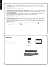
contents
1 - Power Head
1 - Blower Pipe Assembly
1 - Operator's Manual
1 - Warranty Registration Card


