


6
6
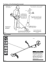
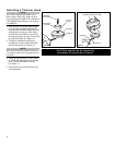
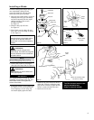
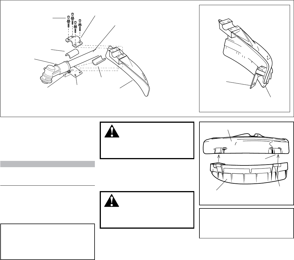
Figure 9
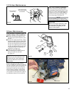
Cutting Attachment Shield
Install the Cutting Attachment Shield
C3410.
1. Insert the cutting attachment shield
between the outer tube and the cutting
attachment mounting plate.
See Figure 9.
WARNING!
NEVER operate the unit without the
cutting attachment shield installed
and tightly secured!
CAUTION!
Make sure the clamp screw and
retaining nut are securely tightened
before tightening the four socket-head
cap screws.
NOTE:
It may be necessary to loosen the retaining
nut and clamp screw to adjust cutting attach-
ment shield mounting plate.
2. Fit the two shims and the bracket over
the outer tube and loosely install the
four socket-head screws. See Figure 9.
3. Tighten the four socket-head cap screws
to secure the cutting attachment shield.
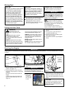
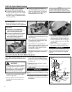
Assembly
Sub-Shield C3410.
(when trimmer head is in use)
1. Attach the shield extension to the
cutting attachment shield. See figure 9B.
WARNING!
NEVER use this machine without sub-
shield when using a trimmer head.
CAUTION!
Make sure the sub-guard is
completely hooked at the hook
receiver.
Sub-shield
Hook
Hook
Receiver
Cutting Attachment Shield
Outer
Tube
Socket-
Head Cap
Screw
Clamp
Screw
Retaining
Nut
Cutting
Attachment Mounting
Plate
Shim
Shim
Bracket
Cutting
Attachment
Shield
Line Cutter
Figure 9A
Cutting Attachment Shield
Sub-shield
with Line
Figure 9B