


13
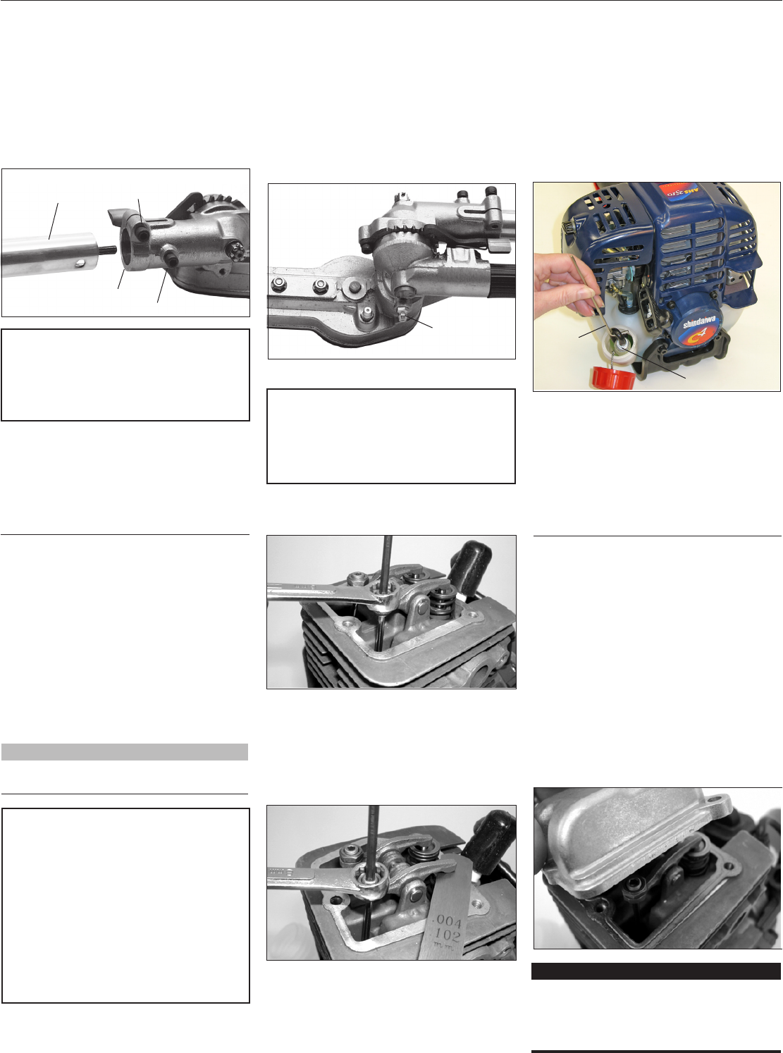
Servicing the fuel lter
CAUTION!
Make sure you do not pierce the fuel
line with the end of the hooked wire.
The line is delicate and can be dam-
aged easily.
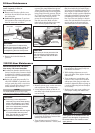
50-Hour Maintenance
Every 50 hours of operation
(more frequently in dusty or
dirty conditions):
n Remove and clean the cylinder cover
and clean dirt and debris from the cylin-
der cooling fins.
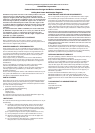
n Lubricate the gearcase. To perform
this operation, first remove the gearcase
from the outer tube as follows:
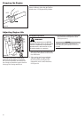
Figure 30
Outer Tube
Gearcase
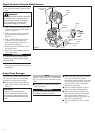
CAUTION!
Do not remove the D-shaped shim
washer from the gearcase clamp! The
shim washer prevents damage from
overtightening the tube clamp screw.
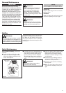
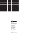
Gearcase
Clamp Bolt
Index Bolt
Figure 31
Gearcase
Grease Fitting
a. Loosen the gearcase clamp bolt.
b. Remove the index bolt from the
gearcase.
139/150-Hour Maintenance
NOTE:
The NGK CMR5H also meets the require-
ments for electro magnetic compliance (EMC).
Valve Adjustment
1.
Remove cylinder cover, rocker arm cover,
and set piston at TDC-compression.
2. Loosen adjuster locknut so that the 2.5
mm Allen socket head adjustment screw
can turn freely.
3. Insert feeler gauge .004” (0.10 mm) for
both inkake and exhaust; between valve
stem tip and rocker arm.
4. Turn adjustment screw (clockwise =
tighter, counter-clockwise = looser) until
CAUTION!
n Performing a valve adjustment
incorrectly may cause hard starting
and/or can damage the unit. Refer
to the C-4 Service Manual for com-
plete valve adjustment procedure
and torque specications.
n If you are unfamiliar with this engine
or uncomfortable with this proce-
dure, Consult with an authorized
Shindaiwa servicing dealer.
feeler gauge is almost snug. Back off
just enough to allow gauge to slip out
with limited resistance.
5. While holding adjustment screw in
place with Allen driver, tighten locknut
with wrench.
6. Turn engine over several times, and
return to TDC-compression. Recheck
with proper feeler gauge to make sure
clearance adjustment did not change as
a result of tightening locknut. Readjust
as necessary.
7. Replace rocker arm cover gasket to as-
sure proper sealing and install cover.
c. Slide the gearcase out of the tube. Using
a grease gun, pump lithium-base grease
(about 10 grams) into the grease fitting
on the gearcase until you see old grease
being purged from the gearcase (Figure
31). Purged grease will be visible in the
outer tube cavity. Clean up excess
grease, then reassemble the gearcase
onto the outer tube. Make sure the
index bolt fits into the hole on the outer
tube. Securely tighten both bolts.
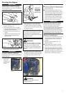
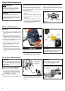
n Use a wire hook to extract the fuel
filter from inside the fuel tank (Figure
32). Inspect the fuel filter element. If it
shows signs of contamination from de-
bris, replace it with a genuine Shindaiwa
replacement fuel filter element. Before
reinstalling the filter, inspect the fuel
line. If you discover damage or deterio-
ration, the unit should be removed from
service until it can be inspected by a
Shindaiwa-trained service technician.
IMPORTANT!
If new gasket is not available and/or old
gasket is not damaged, old gasket may
be reused. Never use cracked or dam-
aged gaskets!
Maintenance after rst 139-hours,
then every 150-hours thereafter.
n Combustion chamber should be decar-
bonized, and the valve clearance should
be adjusted. It is highly recommended
that this is done by a Shindaiwa-trained
service technician.
n Replace the spark plug annually: Use
only NGK CMR5H or equivalent resis-
tor type spark plug of the correct heat
range. Set spark plug electrode gap to
0.024-0.028 inch (0.6 -0.7 mm).
Filter Element
Hooked
Wire
Figure 32