


97-6132, 97-6151 • REV. 11/04
OPERATOR’S MANUAL
PRESSURE WASHER
12
97-6132, 97-6151 • REV. 11/04
13
PRESSURE WASHER
OPERATOR’S MANUAL
Rupture Disk:
If pressure from pump or thermal expansion should
exceed safe limits, the rupture disk will burst allow-
ing high pressure to be discharged through hose to
ground. When disk ruptures it will need to be replaced.
The replacement rupture disk should be torqued to 35
ft. lbs.
Fuel:
Use clean fuel oil that is not contaminated with water
and debris. Replace fuel lter and drain tank every 100
hours of operation.
Use No. 1 or No. 2 Heating Oil (ASTM D306) only.
NEVER use gasoline in your burner tank. Gasoline is
more combustible than fuel oil and a serious explo-
sion could result. NEVER use crankcase or waste oil
in your burner. Fuel unit malfunction could result from
contamination.
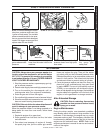
Fuel Control System:
These machines utilize a fuel solenoid valve located
on the fuel pump to control the ow of fuel to the com-
bustion chamber. This solenoid valve, which is normally
closed, is activated by a ow switch when water is ow-
ing through it. When an operator releases the trigger on
the spray gun, the ow of water through the ow switch
stops, turning off the current to the fuel solenoid. The
solenoid then closes, shutting off the supply of fuel to
the combustion chamber. Controlling the ow of fuel in
this way allows for an instantaneous burn or no burn
situation, thereby eliminating high and low water tem-
peratures, and combustion smoke normally associated
with machines incorporating a spray gun.
CAUTION: Periodic inspection is recommended to in-
sure that the fuel solenoid valve functions properly. This
can be done by operating the machine and checking to
see that when the trigger on the spray gun is in the off
position, the burner is not ring.
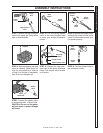
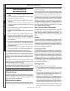
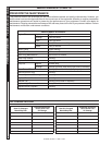
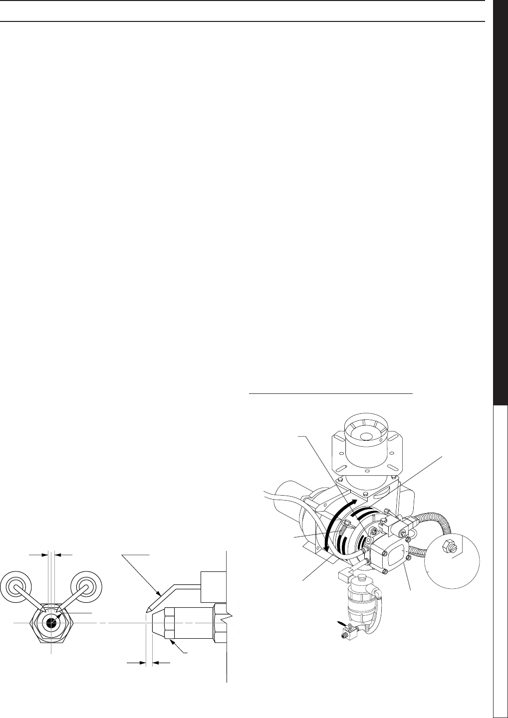
Electrode Setting:
(See illustration below.)
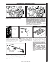
Burner Nozzle:
Keep the tip free of surface deposits by wiping it with a
clean, solvent-saturated cloth, being careful not to plug
or enlarge the nozzle. For maximum efciency, replace
the nozzle each season.
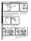
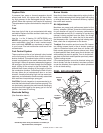
Air Adjustment:
Machines are preset and performance tested at the
factory - elevation 100 feet. A one-time initial correction
for your location will pay off in economy, performance
and extended service life. If a smoking or eye-burning
exhaust is being emitted from the stack, two things
should be checked. First, check the fuel to be certain
that kerosene or No. 1 home heating fuel is being used.
Next, check the air adjustment on the burner.
To adjust: Start machine and turn burner ON. Loosen
two locking screws found in the air shutter openings
(refer to illustration below) and close air shutter until
black smoke appears from burner exhaust vent. Note
air band position. Next, slowly open the air shutter until
white smoke just starts to appear. Turn air shutter half-
way back to the black smoke position previously noted.
Tighten locking screws.
If the desired position cannot be obtained using only
the air shutter, lock the air shutter in as close a position
as can be obtained, then repeat the above procedure
on the air band setting.
Periodically check wiring connections. If necessary to
adjust electrodes, use diagram.
Top View
Side View
5/32"
1/4"
5/32"
Nozzle
Electrode
FUEL AIR ADJUSTMENT
Pressure
Gauge
Port
Pressure
Adjustment
Screw
7-00098 Fuel
Pump
To Fuel
Tank
Air Band
Air Band
Adjustment
Screw
Return Line
MAINTENANCE