


3
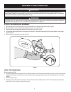
CARTON CONTENTS
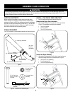
Before installing this accessory, remove all parts from the carton.
Carton contents, including items included within the hardware pack,
are shown in Figures 1 and 2. Part numbers are shown in parentheses
and each item has been identified with a letter code, [X], for use when
following the assembly instructions. Reference to right or left side of
the mower is observed from the operating position.
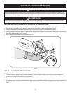
Figure 4
Figure 3
Figure 1
WARNING
Before installing this accessory, shut the engine off and allow it to cool. Disconnect the spark plug wire from the spark plug. Refer to the
mower’s Operator’s Manual for complete safety instructions. Do not operate the mower without the entire grass bag in place. Turn the mower
off and disconnect the spark plug before emptying the grass bag.
ASSEMBLY AND OPERATION
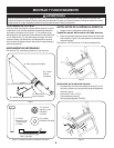
Figure 2 - Contents of the hardware pack.
[F] - HH Cap Screw,
1/4-20 x 1.75” (Qty. 4)
(710-0136)
[A] - Grass bag (764-04052)
[B] - Chute
Assembly
(931-04239)
[C] - Rod Assembly (647-04110-0637)
[D] - Rod Hanger (747-04671)
[E] - Rod Bracket
(787-01569-0637)
[G] - Lock Cap Nut,
1/4-20 (Qty. 4)
(712-0442)
[H] - Washer (Qty. 8)
(736-0463)
[I] - Cable Tie (Qty. 1)
(726-0209)
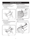
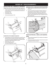
INSTALL THE RIGHT SIDE BRACKET
Shut off engine and disconnect the spark plug wire.
Remove the Right Side Hardware
Remove the following from the right side of the upper handle,
Figure 3. The hardware removed can be discarded.
Two 1/4-20 screws
Two flat washers
Two 1/4-20 cap lock nuts
1.
2.
•
•
•
TOOLS REQUIRED
Two 7/16” wrenches or two adjustable wrenches, and one set of pliers.
Install the Right Bracket
Align holes in rod assembly [C] with holes in panel and secure
with the following items from the hardware pack, Figure 4:
Two 1/4-20 x 1.75” screws [F]
Four flat washers [H]
Two 1/4-20 cap lock nuts [G]
3.
•
•
•
C
F
H
H
G