


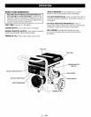

IMPORTANT: Before any attempt to start your generator
be sure to check engine oil (See OPERATION under
Adding Engine Oil on page 12.)
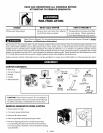
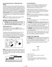
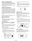
GROUNDING THE GENERATOR
This generator should be grounded to help prevent
accidental electrical shock. Shown below is a picture of
the grounding lug supplied on your generator. First, drive
a 3/4" or 1" diameter copper pipe or rod into the ground
close to the generator set. The pipe must penetrate moist
earth. Using #10 gauge wire, connect one end of the wire
into the grounding lug. Next, connect the other end of the
wire to the copper pipe or rod using an approved ground
clamp.
Grounding Lug
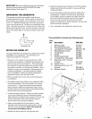
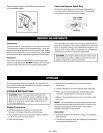
INSTALLING WHEEL KIT
The Sears Wheel Kit was designed to greatly improve the
portablility of your generator. You will need (2) 1/2"
wrenches and (2) 9/16" wrenches.
• Place two 4"x4" pieces of wood on the floor. With
another person helping, carefully lift the generator and
place on top of the wood supports. This will support
the weight of the gasoline engine and generator while
the wheels, brackets, and handle are installed. Also, it
will allow access to the underside of the generator for
hardware installation. Fuel tank should be drained
prior to installation. Make sure that the generator is
supported evenly, level and will not fall.
• Place a handle cap (7) onto each end of handle prior
to installation.
• The handle should be installed on the electrical outlet
end of the generator. Place one washer (12) on long
cap screws (11). Align the handle brackets with the
upper holes pre-drilled in the generator frame. Place
mentioned screws through frame and handle brackets.
Secure with lock nuts (8) and tighten.
• Locate the engine support. Place one wheel bracket
(4) on top of support as shown in illustration below.
Align with the pre-drilled holes in support. Place 2 cap
screws (9) through holes in bracket and support.
Secure with 2 lock nuts (8) and tighten.
• Insert one shoulder bolt (2) into wheel (1).Insert
threaded end of bolt through wheel bracket, secure
with lock nut (3) and tighten. Note: The wheel will
not rub frame if installed properly.
• Repeat the above steps for the opposite side.
• Insert the threaded stud of rubber foot (10) through the
middle hole of the foot bracket (5). Secure with lock
nut (8)and tighten.
• Locate the support under the electrical outlet end of
the generator. Position foot bracket (5),with rubber
foot installed, under the support and align the holes
in the foot bracket (5) with the slots in the support.
Place one cap screw (9)through each slot in the
support and the holes in the foot bracket. Secure with
the lock nuts (8)and tighten.
• Once completed, the wheel kit is ready for use.
This portability kit includes the following parts:
Key
No. Description PART NO.
1 Wheel (2 used) AC-0014
2 Shoulder Bolt (2 used) CAC-60
3 Lock Nut 3/8"-16 (2 used) SSF-8111 -ZN
4 Wheel Bracket (2used) GS-0561
5 Foot Bracket GS-0562
6 Handle GS-0564
7 Handle Cap (2 used) GS-0565
8 Lock Nut 5/16"-18 (9 used) SSF-8150
9 Cap Screw 5/16"-18 x 3/4"
(7 used) SS-12-CD
10 Isolator Foot GS-0587
11 Cap Screw 5/16-18 x 1.75"
(2 used) SSF-999-1
12 Washer (2 used) SS-6506-CD
/
/
/
11
12
10
9 -- ENG