


OPERATION
HOW TO USE YOUR LAWN MOWER
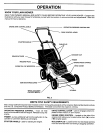
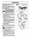
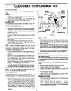
ENGINE SPEED (See Fig. 6)
The engine speed is controlledby a lever locatedon the
sideof the engine. Fast (,Pep)positionis for startingthe
engine, normal cutting,and better grass bagging.Slow
(_ ) positionisforlightcutting,trimmingandfuel economy.
ENGINE ZONE CONTROL
&
CAUTION: Federal regulations require
an engine control to be installed on this
lawn mower in order to minimize the
risk of blade contact injury, Do not
under any circumstances attempt to
defeat the function of the operator con-
trol. The blade turns when the engine is
running.
• Your lawn mower is equipped with an operator pres-
ence control bar which requires the operator to be
positioned behind the lawn mower handle to start and
operate the lawn mower.
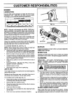
DRIVE CONTROL (See Fig. 7)
• Self-propelling is controlled by holding the operator
presence control bar down to the handle and pushing
the drive control lever forward until it clicks; then
release the lever.
• Forward motion will stop when the operator presence
control bar is released. To stop forward motion without
stopping engine, release the operator presence control
bar slightly until the drive control disengages. Hold
operator presence control bar down to handle to con-
tinue mowing without self-propelling.
To keep drive control engaged when turning corners,
push down on handle and lift front wheels off ground
while turning lawn mower.
TO CONVERT MOWER
Your lawn mower was shipped ready to be used as a
mulcher. To convert to rear bagging or side discharging,
see "TO CONVERT MOWER" in Assembly section of this
manual.
CAUTION: BEFORE ATTEMPTING TO
CONVERT LAWN MOWER:
• Release control bar to stop engine.
• Make sure the blade and all moving parts
have completely stopped.
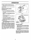
TO ADJUST cu'n'ING HEIGHT (See Fig. 8)
• Raise wheels for low cut and lower wheels for high cut.
• Wheels are set in low cut for shipping. Adjust cutting
height to suit your requirements. Medium position is
best for most lawns.
To change cutting height, squeeze adjuster lever to-
ward wheel. Move wheel up or down to suit your
requirements. Be sure all wheels are in the same
setting.
ENGINE SPEED
CONTROL
LEVER
FIG. 6
OPERATOR PRESENCE
CONTROLBAR
DRIVE
DRIVE CONTROL
CONTROL
LOWER WHEELS
FOR HIGHCUT RAISE WHEELS
FOR LOW CUT
FIG. 8
9