


'JJIL
SERVICE AND A
DJUSTMENTS
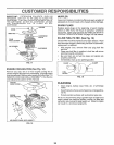
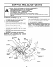
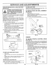
TO ADJUST MOTION CONTROL LEVER
(See Fig. 30)
The motion control lever has been preset at the factory and
adjustment should not be necessary.
If for any reason the motion control lever will not hold its
position while at a selected speed, it may be adjusted atthe
friction pack located on the right side of transmission
° Park tractor on level surface. Stop tractor by turning
ignition key to "OFF" position, and engage parking
brake.
o Adjust motion control lever by tightening adjustment
iocknut one half (1/2) turn.
NOTE: If for any reason the effort to move the motion
control lever becomes too excessive, reverse the above
TO ADJUST STEERING WHEEL ALIGNMENT
If steering wheel crossbars are not horizontal (left to right)
when wheels are positioned straight forward, remove steer-
ing wheel and reassemble per instructions in the Assembly
section of this manual,
FRONT WHEEL TOE-IN/CAMBER
The front wheel toe-in and camber are not adjustable on
your tractor, If damage has occurred to affect the front
wheel toe-in or camber, contact your nearest authorized
service center/department
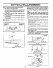
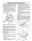
TO REMOVE WHEEL FOR REPAIRS
(See Fig. 31)
adjustment procedure by loosening !ocknut 1/4 to 1/2 turn
Road test tractor after adjustment and repeat procedure if
necessary,
TRANSMISSION REMOVAL/REPLACEMENT
Should your transmission require removal for service or
replacement, it should be purged after reinsta!lation and
before operating the tractor, See "PURGE TRANSMiS-
SION" in the Operation section of this manual..
ADJUSTMENT
LOCKNUT
FIG. 30
. Block up axle securely
o Remove axle cover, retaining ring and washers to allow
wheel removal (rear wheel contains a square key - Do
not lose)
o Repair tire and reassemble
o On rear wheels only: align grooves in rear wheel hub
and axle lnsed square key,
o Replace washers and snap retaining ring securely in
axle groove.,
° Replace axle cover
WASHERS
RETAINING
RING
I AXLE COVER
I
"_SQUAREKEY
--(REAR WHEELONLY)
FIG. 3t
25