


SERVICE AND ADJUSTMENTS
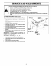
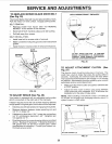
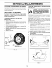
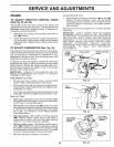
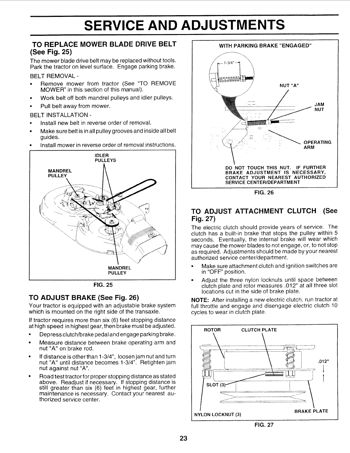
TO REPLACE MOWER BLADE DRIVE BELT
(See Fig. 25)
The mower blade drive belt may be replaced without tools.
Park the tractor on level surface. Engage parking brake.
BELT REMOVAL-
• Remove mower from tractor (See "TO REMOVE
MOWER" in this section of this manual).
• Work belt off both mandrel pulleys and idler pulleys.
• Pull belt away from mower.
BELT INSTALLATION -
• Install new belt in reverse order of removal.
• Make sure belt isin all pulley grooves and inside all belt
guides.
• Install mower in reverse order of removal instructions.
IDLER
PULLEYS
MANDREL
PULLEY
MANDREL
PULLEY
FIG. 25
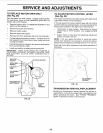
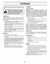
TO ADJUST BRAKE (See Fig. 26)
Your tractor is equipped with an adjustable brake system
which is mounted on the right side of the transaxle.
If tractor requires more than six (6) feet stopping distance
at high speed in highest gear, then brake must be adjusted.
• Depress clutch/brake pedal and engage parking brake.
• Measure distance between brake operating arm and
nut "A" on brake rod.
If distance is other than 1-3/4", loosen jam nut and turn
nut "A" until distance becomes 1-3/4". Retighten jam
nut against nut "A".
Road test tractor for proper stopping distance as stated
above. Readjust if necessary. If stopping distance is
still greater than six (6) feet in highest gear, further
maintenance is necessary. Contact your nearest au-
thorized service center.
WITH PARKING BRAKE "ENGAGED"
DO NOT TOUCH THIS NUT. IF FURTHER
BRAKE ADJUSTMENT IS NECESSARY,
CONTACT YOUR NEAREST AUTHORIZED
SERVICE CENTEWDEPARTMENT
FIG. 26
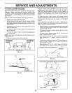
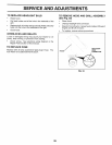
TO ADJUST A'I-i'ACHMENT CLUTCH (See
Fig. 27)
The electric clutch should provide years of service. The
clutch has a built-in brake that stops the pulley within 5
seconds. Eventually, the internal brake will wear which
may cause the mower blades to not engage, or, to not stop
as required. Adjustments should be made by your nearest
authorized service center/department.
• Make sure attachment clutch and ignition switches are
in "OFF" position.
• Adjust the three nylon Iocknuts until space between
clutch plate and rotor measures .012" at all three slot
locations cut in the side of brake plate.
NOTE: After installing a new electric clutch, run tractor at
full throttle and engage and disengage electric clutch 10
cycles to wear in clutch plate.
ROTOR CLUTCH PLATE
.012"
NYLON LOCKNUT (3)
FIG. 27
BRAKE PLATE
23