


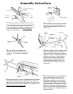
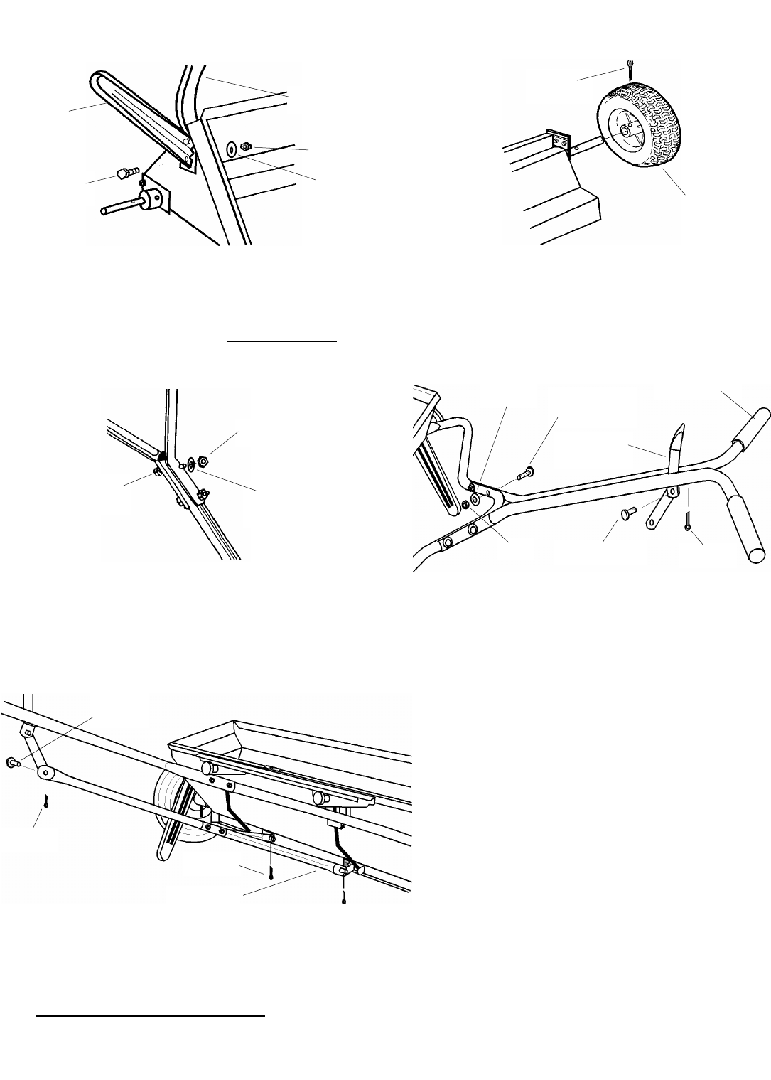
1. Remove spreader and components from carton.
Place Hopper on it’s front panel, insert two (2) 1/4-20
X 1/2” Hex Head Bolts through the Leg, flattened
end of Handle Brace, and holes in Hopper as shown.
Install Lockwashers and Nuts but do not tighten
.
Repeat on opposite side.
Assembly Instructions
2. Slide Wheels onto each end of Axle with
the longer portion of the Wheel facing the
Hopper. Secure Wheels with 3/16 dia. x 2”
Cotter Pins.
4. Stand spreader upright on Wheels. Attach
Upper Handle assembly to Handle Brace
(make sure Handle is positioned as shown)
using (4) 1/4-20 X 1 1/2” Hex Bolts, (4) Lock
Washers, and (4) Nuts. Tighten securely.
Install Handle Grips onto Upper Handle.
Slide Handle Lever assembly between
Handle Brackets and secure with 1/4 dia,
Clevis and Cotter Pin. Make sure Lever
pivots freely.
3. Install Control Tube between the
Control Tube Braces and secure with (2)
1/4-20 X 1 1/2” Hex Bolts, Lockwashers,
and nuts.
5. Slide the ends of the Control Tube Braces over the Studs on
the Shutoff Bar Brackets, secure with Cotter Pins. Attached
opposite end of Control Tube to the Handle Lever using 1/4 dia.
Clevis and Cotter Pin. Make sure Handle Lever operates freely.
Tighten all Nuts left loose in step #1.
I
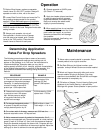
6. To check spreader for completed shutoff,
pull the Handle Lever back to the “OFF”
position. Turn spreader over to see if the
Shutoff Bar completely covers the holes in
the bottom of the Hopper. If not, stand the
spreader upright on Wheels push the Handle
Lever forward to the “ON” position. Loosen
the Bolts in the Hopper holding the Handle
Brace. Push down on the Handle Brace and
the front of the Hopper. Retighten Bolts and
check the shutoff.
Leg
Handle Brace
Nut
3/16 X 2”
Cotter Pin
Drive Wheel
1/4-20 X 1 1/2”
Hex Bolt
Nut
Nut
1/4-20 X 1 1/2”
Hex Bolt
Lock
Washer
Handle Grip
Handle Lever
Assembly
1/4” D. Clevis
Cotter
1/4” D.
Clevis
Cotter
Cotter
Control Tube
Brace
1/4-20 X 1/2”
Hex Bolt
Lock
Washer
Lock
Washer