


8
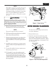
STEERING CONTROL ROD
ADJUSTMENT
-NOTE-
This adjustment is made to allow the steering
control levers to be moved out of the neutral
latch without engaging reverse.
1. Connect the steering control rods into the steer-
ing control levers on the handle. Do not install
the hair pin at this time.
2. Turn the swivel joint on the steering control rods
until the swivel joint is centered in the slot in the
bellcrank.
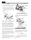
3. Remove the steering control rods from the
machine. Install the speed control spring onto
the swivel joint. Reinstall the steering control
rods onto the machine and secure using the hair
pins.
-NOTE-
Before proceeding with this adjustment, be sure
that the tire pressures are correct. (see page 4)
and that the neutral adjustment and the steering
control rod adjustment have been completed.
1. Engage the neutral latch on both steering control
levers and move the speed adjustment lever into
the neutral position.
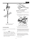
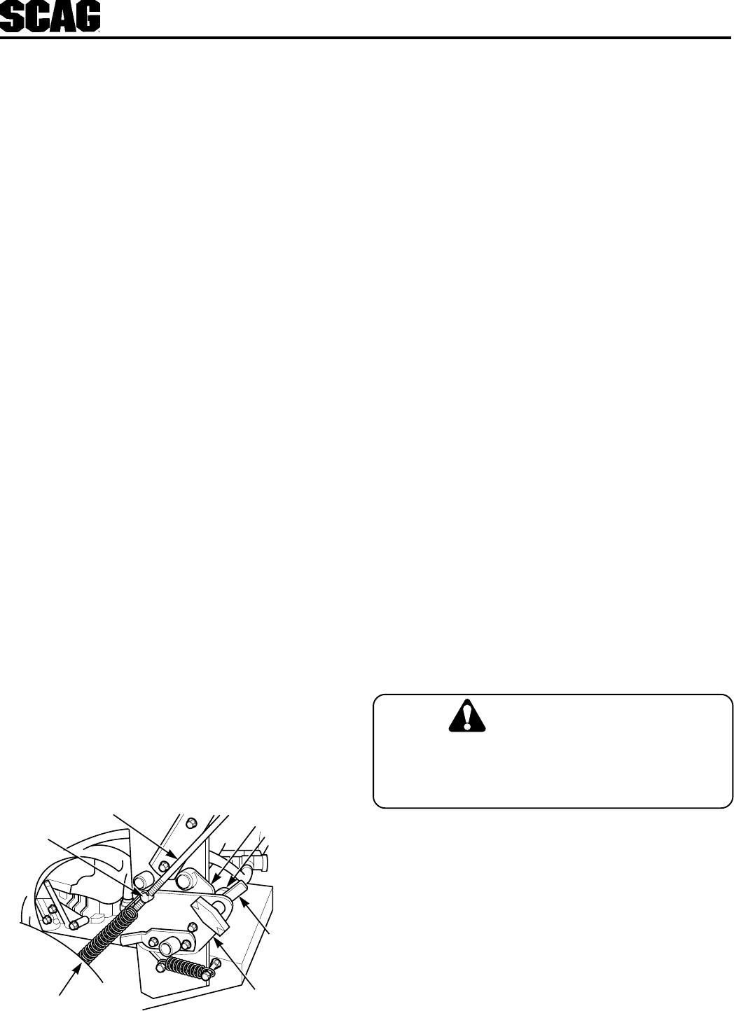
2. Position the speed adjustment lever so that the
bearing just contacts the speed adjustment cam.
(See below)
Steering Control Rod
Speed Control Spring
Bellcrank
SC161G
Swivel
Joint
Speed Adjustment
Cam
Bearing
Speed
Adjustment
Bearing Lever
TRACKING ADJUSTMENT
3. Tighten the bearing securing the speed adjustment
bearing lever and repeat on the opposite side.
4. With the machine on a flat level surface, start the
engine and place the speed adjustment lever into
the speed that will most often be used.
5. Squeeze the steering control levers and release
the neutral latch. Slowly release the steering
control levers, allowing the machine to move for-
ward.
6. If the machine pulls to one side, put the speed
adjustment lever back into the neutral position
and turn the engine off.
7. On the side that the machine pulled toward,
loosen the wing nut securing the speed adjust-
ment bearing lever and move the bearing 1/16"
away from the cam. Start the engine and recheck
the tracking. Adjust as needed.
8. If tracking cannot be achieved, contact your Scag
servicing dealer.
PARKING BRAKE
1. Adjust the parking brake so that when the brake
hand lever is against the stop on the handle bar,
the brake levers on the brake shaft weldment are
against the stops on the engine deck.
Adjust the brake only enough to hold the
machine. Excessive force may cause damage
to the machine or brake components.
2. Adjust the brake actuator rod on either side of
the machine to obtain proper brake adjustment.
CAUTION: