12
R
Section 4
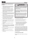
CAUTION
Do not attempt to operate this mower unless you
have read this manual. Learn the location and
purpose of all controls and instruments before
you operate this mower.
CONTROLS AND INSTRUMENT 4.1
IDENTIFICATION
Before operating the mower, familiarize yourself with all
mower and engine controls. Knowing the location, function
and operation of these controls is important for safe and
efficient operation of the mower.
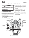
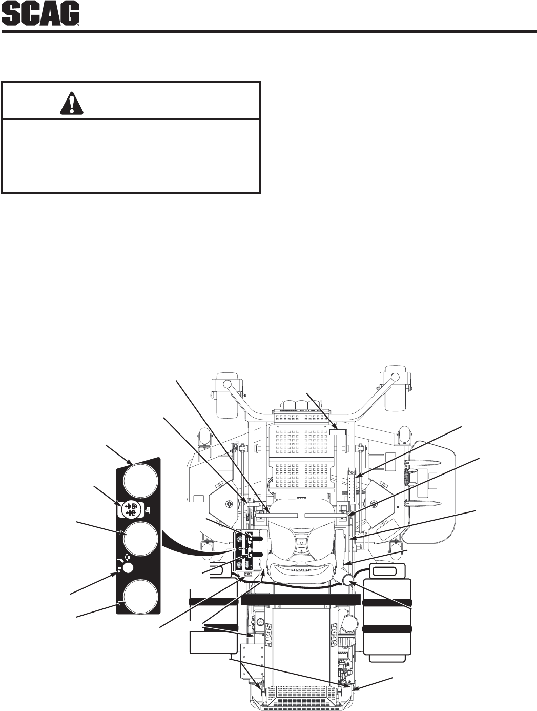
Ignition Switch (Figure 4-1).1. The ignition switch
is used to start the engine and has three positions;
OFF, ON, and START.
OPERATING INSTRUCTIONS
Mower Deck Switch (Figure 4-1). 2. Used to engage
and disengage the mower drive system. Pulling up
on the switch will engage the deck drive. Pushing
down on the switch will disengage the deck drive.
Engine Choke Control (Figure 4-1).3. Used to start
a cold engine.
Engine Throttle Control (Figure 4-1).4. Used to
control the engine speed. Pushing the lever forward
increases engine speed. Pulling the lever back
decreases engine speed. Full back position is the
IDLE position. Full forward is the cutting position.
Voltmeter (Figure 4-1).5. Indicates the condition of
the charging system. When the engine is running, in
normal operating conditions, the needle should be in
the 12 to 14 volt range.
H
aljalefja
irjf;o3rf
afkrjf;w
sorgf
aljalefja
irjf;o3rf
aljalefja
irjf;o3rf
OFF
OFF
OFF
LEFT STEERING
CONTROL
HOURMETER
RIGHT STEERING
CONTROL
DECK LIFT
DECK RELEASE
PARKING BRAKE
CONTROL
CUTTING HEIGHT
ADJUSTMENT
SEAT BELT
WATER TEMPERATURE
OFF
ON
START
MOWER DECK
PULL OUT TO ENGAGE
PUSH IN TO DISENGAGE
MOWER DECK SWITCH
OIL PRESSURE
IGNITION SWITCH
VOLTMETER
FUEL SELECTION
SWITCH
FUEL GAUGE
LP
GAS
ENGINE
THROTTLE
CONTROL
FUSES
DUMP VALV E
CHOKE
481348
ENGINE
CHOKE
CONTROL
Controls and InstrumentsFigure 4-1.


