


20
R
Section 6
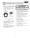
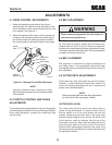
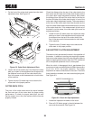
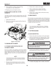
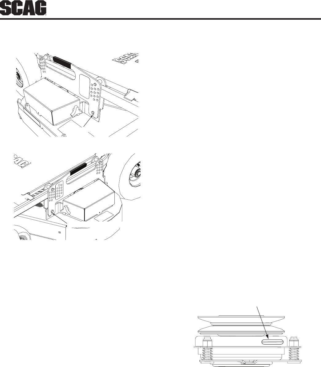
On the front of the cutter deck locate the cutter deck 1.
adjustment slots. See Figure 6-2.
ADJUSTMENT SLOT
ADJUSTMENT SLOT
Cutter Deck Adjustment SlotsFigure 6-2.
Loosen the two (2) elastic stop nuts. Adjust the cutter 2.
deck up or down in the adjustment slot to adjust until
the distance from the top of the cutter deck to the
floor is the same as the measurement on both sides
of the machine.
Tighten the two (2) elastic stop nuts to secure the 3.
cutter deck in the proper position.
CUTTER DECK PITCH
The pitch of the cutter deck should be equal between
the front and rear of the cutter deck for proper cutting
performance. To check for proper deck pitch, be sure
that the mower is on a flat, level surface and the tires are
properly inflated.
Check the distance from the top of the cutter deck to the
floor at the rear RH side of the cutter deck directly behind
the cutter deck height adjustment bracket. Next check
the distance from the top of the cutter deck to the floor at
the front RH side of the cutter deck directly in front of the
cutter deck height adjustment bracket. The measurement
at the front of the cutter deck should be the same as the
rear of the deck. Make these measurements at the LH side
of the cutter deck also. If the measurement at the front of
the deck is not the same, the cutter deck pitch must be
adjusted as follows:
Loosen the two (2) elastic stop nuts. Adjust the cutter
1.
deck up or down in the adjustment slot to adjust until
the distance from the top of the cutter deck to the
floor is the same as the measurement on both sides
of the machine.
Tighten the two (2) elastic stop nuts to secure the 2.
cutter deck in the proper position.
ELECTRIC CLUTCH ADJUSTMENT6.6
The electric clutch serves two functions in the operation of
the mower. In addition to starting and stopping the power
flow to the cutter blades, the clutch also acts as a brake to
assist in stopping blade rotation when the PTO is switched
off or the operator presence circuit is interrupted.
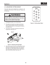
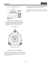
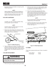
When the clutch is disengaged, the air gap between the
armature and rotor must be adjusted to fifteen thousandths
of an inch, 0.015, for proper operation. The airgap
adjustment is made at three bolts on the clutch. There are
three inspection windows, one next to each adjusting bolt.
See Figure 6-3.
INSPECTION WINDOW (x3)
Clutch Air Gap AdjustmentFigure 6-3.
Locate the inspection windows on the clutch.1.
Place a 0.015 feeler gauge in the slot between the 2.
rotor and the armature. See Figure 6-4.