


13
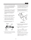
6. Install the blower mounting bracket to the deck
using 1/2-13 x 1-1/2" hex head bolts (p/n 04001-
71), 1/2" spring lockwashers (p/n 04030-06), and
1/2-13 elastic stop nuts (p/n 04021-07). See
Figure 5-3, Page 12. Do not fully tighten the
hardware at this time.
7. Install the new belt cover from the cutter deck to
the blower mounting bracket and secure with
one of the original belt cover plastic wing nuts.
8. Install the catch plate (p/n 423297) to the blower
assembly using 3/8-16 x 1-1/4" carriage bolts
(p/n 04003-11) facing upward. See Figure
5-3, Page 12. Secure with 3/8" spring
lockwashers (p/n 04030-04) and 3/8-16 elastic
stop nuts (p/n 04021-09). Do not fully tighten the
hardware at this time.
9. Install the blower assembly to the mounting
bracket and secure with the mounting pin and
large hair pin. See Figure 5-3, Page 12.
10. Align the blower assembly with the discharge
opening of the cutter deck. Tighten the
hardware for the mounting bracket. Then
tighten the hardware for the catch plate.
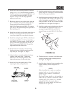
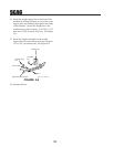
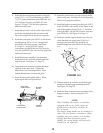
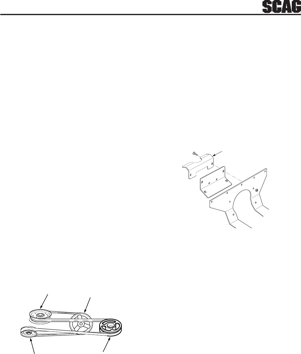
11. Install the belt to the spindle pulley. When
replacing the belt, see figure below.
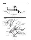
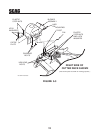
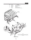
13. Install the hopper mounting brackets (p/n 451512
& p/n 451595) to the outside of the frame on the
rear of the machine using 3/8-16 x 1" hex head
bolts (p/n 04001-19) and 3/8-16 elastic stop nuts
(p/n 04021-09). See Figure 5-6, Page 15.
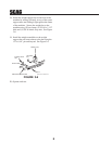
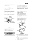
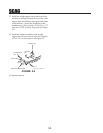
14. Install the catcher support bracket onto the rear
of the machine and secure with 5/16-18 x 1"
carriage bolts (p/n 04003-04) and 5/16-18
serrated flange nuts (p/n 04019-03) See Figure
5-4.
15. With the help of an assistant, install the hopper
assembly into the hopper mounting brackets.
See Figure 5-6, Page 15.
FRONT SIDE
IDLER PULLEY
BACK SIDE
IDLER PULLEY
BLOWER
PULLEY
SPINDLE
PULLEY
Catcher Support Bracket
FIGURE 5-4
12. Install the plastic belt cover and secure with the
plastic wing nuts. See Page 20 of the Illustrated
Parts List for proper installation.
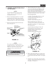
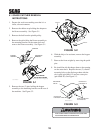
16. Install the hose from the blower assembly to the
hopper assembly. Secure using the 8-1/2"
clamps.
-NOTE-
When installing this catcher on machines
equipped with an air cooled engine the
discharge hose should be shortened to
56" in length.
The hopper dump handle can be installed on
either side for operator convenience. When
installing this grass catcher on a machine
with the Roll Over Protection System
(ROPS), the curved handle will need to be
installed on the right side.