


8
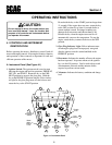
OPERATING INSTRUCTIONS
Do not attempt to drive this mower unless you
have read this manual. Learn the location and
purpose of all controls and instruments before
you operate this mower.
Do not hold the key in the START position longer than
15 seconds. If the engine does not start, return the key
to the OFF position for at least 60 seconds before a
restart attempt is made. Prolonged cranking can
damage the starter motor and shorten battery life.
Release the key when the engine starts and it will
automatically return to the run position. To stop the
engine, rotate the key counter-clockwise to the OFF
position.
2. Glow Plug Indicator Light: Yellow indicator turns
off when glow plugs have been properly energized
after the ignition switch is turned and held in the
PREHEAT position.
3. Hourmeter: Indicates the number of hours the engine
has been operated. It operates whenever the ignition
key is in the ON position. Can be used to keep track
of maintenance intervals and the amount of time
required to perform various tasks.
4. Voltmeter: Indicates the battery condition and charge
level.
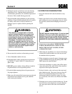
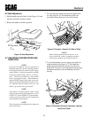
4.1 CONTROLS AND INSTRUMENT
IDENTIFICATION
Before operating the mower, familiarize yourself with all
mower and engine controls. Knowing the location, function
and operation of these controls is important for safe and
efficient operation of the mower.
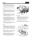
A. Instrument Panel (See Figure 4-1)
1. Ignition Switch: The ignition switch is used to start
and stop the engine and has four positions; PREHEAT,
OFF, ON, and START. Rotate the key to the PRE-
HEAT position to energize the glow plug. Hold the
key at the PREHEAT position until the yellow indica-
tor light for the glow plug turns off, then release and
rotate the key to the START position.
CAUTION:
Section 4
Hourmeter
Temperature Gauge
Fuel Gauge
Voltmeter
Fuse
Holders
Throttle
Lever
Glow Plug
Indicator
Light
Ignition
Switch
Mower
Deck Height
Switch
Mower
Deck Lift
Switch
Blade
Brake
Control
Lever
Engine
Oil Pressure
Switch
1
2
9
10
8
7
6
5
6
4
Figure 4-1 Instrument Panel