


8
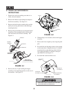
1. Prepare the work area making sure that it is a
clean, safe environment.
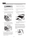
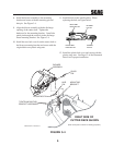
2. Remove the rubber strap holding the adapter to
the blower assembly. See Figure 5-1.
3. Remove the belt from the spindle pulley and the
quick pin securing the blower to the discharge
mounting bracket.
4. Remove the pin and hair pin securing the blower
assembly to the mounting bracket on the cutter
deck and remove the blower assembly. See
Figure 5-1.
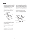
5. Remove the two (2) pins holding the hopper
assembly to the mounting brackets on the rear of
the machine. See Figure 5-2.
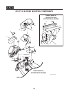
6.1 GRASS CATCHER REMOVAL
INSTRUCTIONS
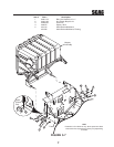
6. With the help of an assistant, remove the hopper
assembly.
7. Remove the front weights by removing the quick
pins.
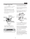
8. Re-install the side discharge chute to the opening
on the cutter deck. Replace the two (2) outside
mounting bolts on the discharge chute with the
clevis pins (p/n 04064-15) and rue cotter pins
(p/n 04069-03). See Figure 5-3.
9. Re-install the cutter deck belt cover.
FIGURE 5-3
REMOVE
REMOVE
PULL HOOD
ASSEMBLY OUT
FIGURE 5-1
FIGURE 5-2
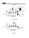
WARNING
WARNING
DO NOT OPERATE WITHOUT DISCHARGE CHUTE, MULCHING
KIT, OR ENTIRE GRASS CATCHER INSTALLED
BLOWER
ASSEMBLY
MOUNTING
BRACKET
PIN & HAIR PIN
ADAPTER
RIGHT SIDE OF
CUTTER DECK SHOWN
(Note: Some parts not shown for viewing purposes.)
2006 GC-STC-V removal art 1
QUICK PIN
CLEVIS PIN
P/N 04064-15
CLEVIS PIN
P/N 04064-1
5
RUE COTTER PIN
P/N 04069-03
DISCHARGE
CHUTE
GC-STC-V removal art 3