


9
NOZZLE
THROTTLE
CABLE
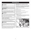
WARNING:
Disconnect the spark plug wire before assembling parts.
Failure to do so could result in possible serious personal
injury.
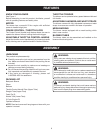
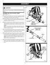
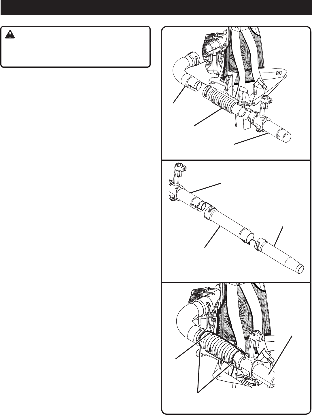
ASSEMBLING THE BLOWER TUBES
See Figures 2 - 4.
��n Assemble the elbow tube onto blower by aligning raised
locking tabs on blower unit with the raised locking slots
on elbow as shown and twist to secure.
n Attach bellows onto elbow tube by aligning raised lock-
ing tabs on elbow tube with the raised locking slots on
bellows and twist to secure.
n Attach throttle control handle tube onto bellows by
aligning raised locking tabs on bellows with the raised
locking slots on throttle control handle tube and twist to
secure.
NOTE: The position of the throttle control handle may be
adjusted for the best comfort after the blower is strapped
onto the operator’s back.
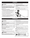
n Join the straight upper tube and nozzle together by align-
ing raised locking tabs on straight upper tube with the
raised locking slots on nozzle and twist to secure.
n Assemble the connected lower tubes to the throttle
control handle tube by aligning raised locking tabs on
the throttle control handle tube with the raised locking
slots on connected lower tubes by twisting to secure.
NOTE: Check all locking connections after initial run to
ensure they are tightly secured.
n Hold the throttle cable against the bellows and install the
cable ties. Cable ties should be tight enough to retain
the throttle cable to the bellows but still allow for move-
ment.
ASSEMBLY
BELLOWS
ELBOW
TUBE
Fig. 2
Fig. 3
Fig. 4
THROTTLE
CONTROL
HANDLE TUBE
(UPPER TUBE)
CABLE TIE
THROTTLE CONTROL
HANDLE TUBE
(UPPER TUBE)
UPPER TUBE
THROTTLE
CONTROL
HANDLE TUBE
(UPPER TUBE)