14
UK
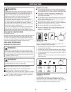
CUTTING SPRING POLES
See Figure 37.
A spring pole (A) is any log, branch, rooted stump, or sapling
which is bent under tension by other wood so that it springs
back if the wood holding it is cut or removed. On a fallen tree,
a rooted stump has a high potential of springing back to the
upright position during the bucking cut to separate the log from
the stump. Watch out for spring-poles: they are dangerous.
WARNING:
Spring poles are dangerous and could strike the operator
causing the operator to lose control of the chainsaw. This
could result in severe or fatal injury to the operator.
DANGER:
Never start the engine before installing the guide bar,
chain, drivecase cover, and clutch drum. Without all these
parts in place, the clutch can fly off or explode exposing
the user to possible serious injury.
WARNING:
To avoid serious personal injury, read and understand
all the safety instructions in this section.
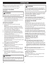
1. Always place the switch in the stop “O” position before you
work on the saw.
2. Make sure the chain brake is not set by pulling the chain
brake lever/hand guard towards the front handle to the
RUN position (A).
See Figure 3.
3. Wear gloves when handling the chain and bar. These
components are sharp and may contain burrs.
4. Remove the bar mounting nuts (B) using a combination
wrench (C) or a 5/8 in. spanner.
5. Remove the clutch cover (D), and the outer guide bar
plate (E).
6. Lay out the saw chain in a loop and straighten any kinks.
The cutters (F) should face in the direction of chain rotation
(G). If they face backwards, turn the loop over.
7. Place the chain drive links (H) into the bar groove (I).
8. Position the chain so there is a loop at the back of the bar.
9. Hold the chain in position on the bar and place the loop
round the sprocket (J).
10. Fit the bar flush against the mounting surface so that the
bar studs (K) are in the long slot of the bar.
NOTE: When placing the bar on the bar studs ensure that
the adjusting pin (L) is in the chain tension pin hole.
11. Replace the outer guide bar plate ensuring that the bar pin
groove is at the bottom with the upper and lower edges
angled away from the guide bar.
12. Replace the clutch cover and bar mounting nuts.
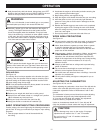
ASSEMBLING THE BAR AND CHAIN
See Figures 3 and 38 to 47.
13. Tighten the bar mounting nuts finger tight only. The bar
must be free to move for tension adjustment.
14. Remove all slack from the chain by turning the chain
tensioning screw (M) clockwise until the chain seats snugly
against the bar with the drive links in the bar groove.
15. Lift the tip of the guide bar up to check for sagging (N).
16. Release the tip of the guide bar and turn the chain
tensioning screw 1/2 turn clockwise. Repeat this process
until sagging does not exist.
17. Hold the tip of the guide bar up and tighten the bar
mounting nuts (O) securely.
The chain is correctly tensioned when there is no sagging on
the underside of the guide bar, the chain is snug, but it can be
turned by hand without binding.
See Figure 47.
Ensure that the
chain brake is not set.
NOTE: If chain is too tight, it will not rotate. Loosen the bar nuts
slightly and turn the tension adjuster 1/4 turn anticlockwise. Lift
the tip of the guide bar up and retighten the bar nuts securely.
Ensure that the chain will rotate without binding.
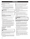
ADJUSTING THE CHAIN TENSION
See Figures 48, 49, and 50.
WARNING:
Never touch or adjust the chain while the motor is
running. The saw chain is very sharp. Always wear
protective gloves when performing maintenance on the chain.
1. Stop the engine before setting the chain tension.
2. Make sure the guide bar nuts are loosened to finger tight and
turn the chain tensioner clockwise to tension the chain.
NOTE: A cold chain is correctly tensioned when there is no
slack on the underside of the guide bar, the chain is snug but
can be turned by hand without binding.
3. Retension the chain whenever the flats on the drive links (A)
hang out of the bar groove.
NOTE: During normal saw operation, the temperature of the
chain increases. The drive links of a correctly tensioned
warm chain (B) will hang approximately 1.25 mm (0.05 in.)
out of the bar groove. To help determine the correct warm
chain tension, the tip of the combination wrench (C) can be
used as a guide.
OPERATION
MAINTENANCE


