


21 - English
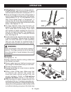
Replace the chain cover, washer and chain
cover screw. Tighten the chain cover screw
finger tight only. The bar must be free to move
for tension adjustment.
Remove all the slack from the chain by turning
the chain tensioning screw clockwise until the
chain seats snugly against the bar with the drive
links in the bar groove.
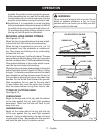
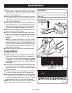
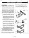
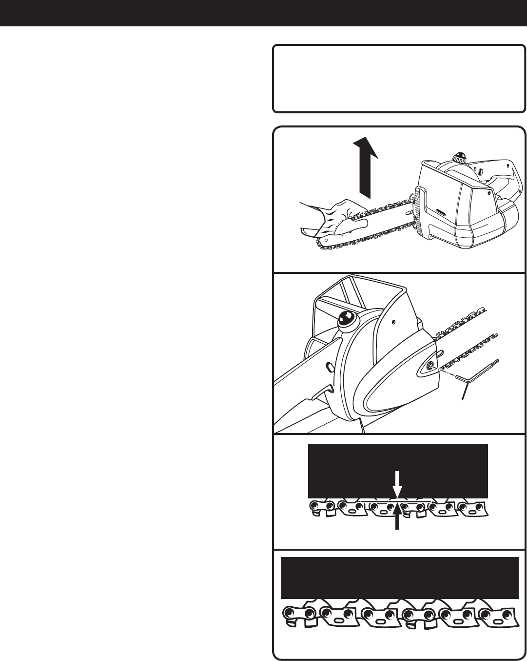
Lift the tip of the guide bar up to check for
sag. Release the tip of the guide bar and turn
the chain tensioning screw 1/2 turn clockwise.
Repeat this process until sag does not exist.
Hold the tip of the guide bar up and tighten the
bar mounting screw securely.
Chain is correctly tensioned when there is no
sag on the underside of the guide bar, the chain
is snug, but it can be turned by hand without
binding.
NOTE: If chain is too tight, it will not rotate.
Loosen the chain cover screw slightly and turn
tension adjuster 1/4 turn counterclockwise. Lift
the tip of the guide bar up and retighten chain
cover screw securely. Assure that the chain will
rotate without binding.
Place the hex key back into the storage area.
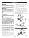
CHAIN TENSION
See Figures 28 - 29.
Stop the engine before setting the chain tension.
Make sure the guide bar screw is loosened to
finger tight, turn the chain tensioner clockwise
to tension the chain. Refer to Replacing Bar
and Chain earlier in this manual for additional
information.
A cold chain is correctly tensioned when there
is no slack on the underside of the guide bar,
the chain is snug, but it can be turned by hand
without binding.
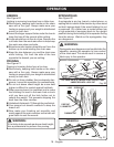
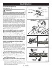
Chain must be re-tensioned whenever the flats
on the drive links hang out of the bar groove.
During normal saw operation, the temperature
of the chain will increase. The drive links of
a correctly tensioned warm chain will hang
approximately .050 in. out of the bar groove.
NOTE: New chain tends to stretch, check chain
tension frequently and tension as required.
MAINTENANCE
CAUTION:
Chain tensioned while warm, may be too tight
upon cooling. Check the “cold tension” before
next use.
Fig. 26
Fig. 27
HEX KEY
LIFT THE TIP OF
THE GUIDE BAR
UP TO CHECK FOR
SAG
APPROX. .050 in.
Fig. 29
FLATS
Fig. 28