English – 15
ASSEMBLY
B
A
L
M
C
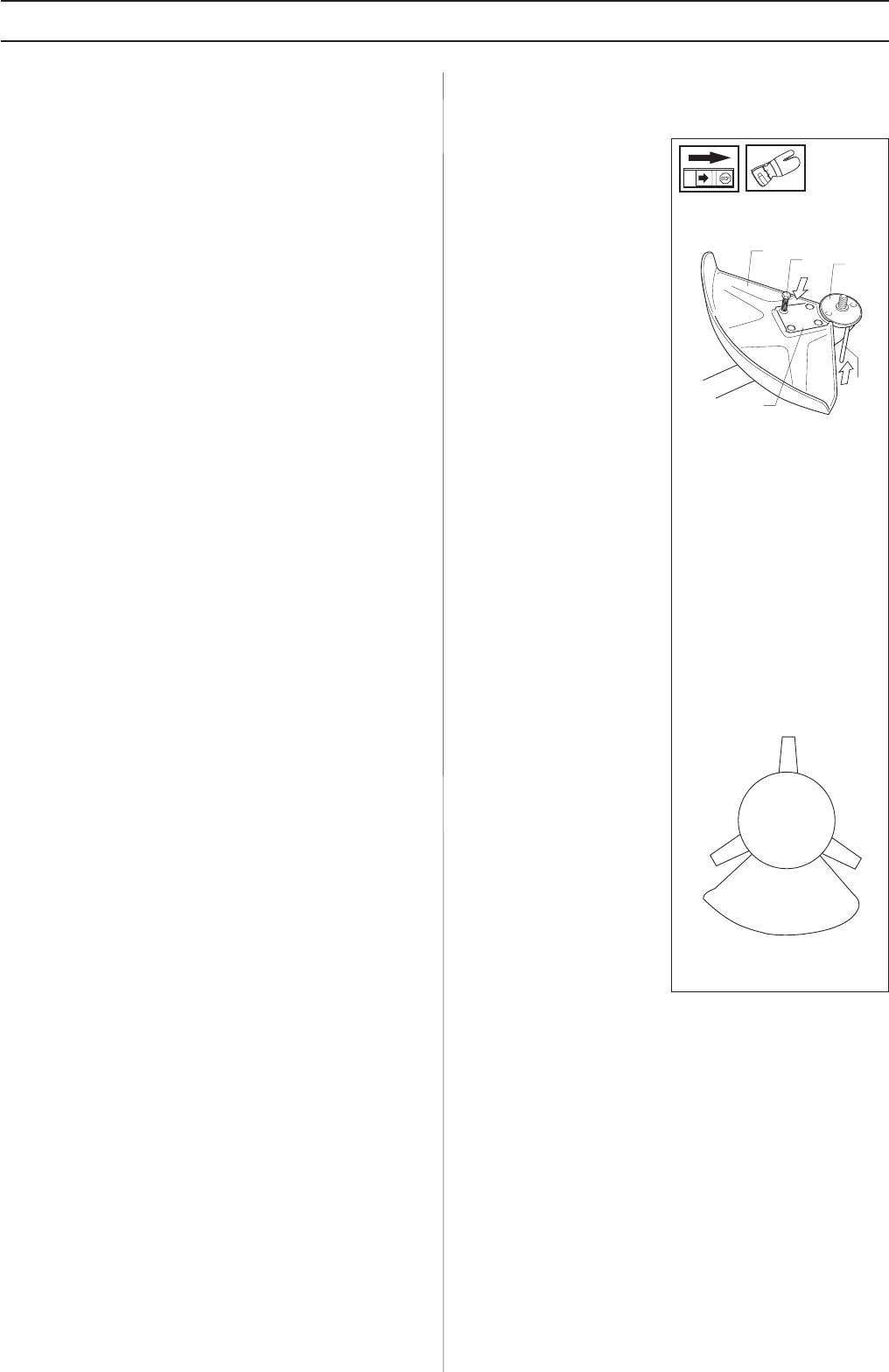
• Fit the guard (A)
intended for use with
the trimmer head.
Secure using four bolts
(L) and the support plate
(M) as shown in the
diagram.
• Fit the disc drive (B) on
the output axle.
• Turn the blade axle until
one of the disc drive’s
holes aligns with the
corresponding hole in
the gear housing.
• Insert the locking pin
(C) into the hole to lock
the axle.
• Screw on the trimmer
head (H) in the
direction of rotation.
• Dismantling takes place
in the reverse order.


