


5
22
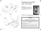
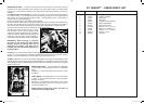
REVERSING CUTTER – A feature of this machine is that the cylinder may be easily removed,
reversed end for end and replaced. This provides a new keen cutting edge. If the bottom blade
is badly worn, this should be replaced at the same time that the cutting cylinder is reversed or
replaced.
To withdraw cutter from machine, first remove cutter chain (7), sprocket (8) and grass deflector
(9), refer illus. Page 1. The sprocket is removed by inserting tommy bar in hole in sprocket and
giving tommy bar a sharp tap with a hammer. NOTE – The sprocket has a left – hand thread, to
unscrew, turn in a clockwise direction.
Remove the grass deflector and deflector supporting bar.
Remove the cutter hanger caps by undoing the holding bolts (10) at each side of the machine. Then
the cutter may be taken from the machine by lifting and moving to the chain side of the machine.
The opposite side will then clear side frame. Continue with a diagonal lift to complete removal.
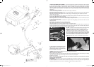
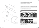
Remove the nut from the end of the cutter (it has a left-hand thread).
Reposition this nut at the other end of the cutter.
Turn the cutter end for end and replace in the
machine. Then reverse operations used to remove
cutter from machine. Replace all bolts and tighten
firmly. After reversing cutter it will be necessary to
adjust same. Also see detail on chain adjustment.
IMPORTANT: When reversing or replacing
the cutter do not remove the cutter bearing
hangers. Remove the bearing caps only as
instruction. The bearing caps must not be
changed over, each cap must be replaced in its
original location.
CLUTCH – To be certain that the clutch is fully engaged without possibility of slip, there should be
approx. 1
1
/
2
” of free movement (at the clutch operating lever knob) before the resistance of clutch
operation is felt. This adjustment is made by means of the self-locking nut “E”.
CHAINS – Adjustment – Loosen chain adjustor locking bolt (14) and slide the chain adjustor in the
desired direction. A chain should never be adjusted tightly. It is advisable to leave the cutter chain
with a little slackness so that slight adjustment of the cutter can be made without having to re-adjust
this chain each time.
GRASS DEFLECTOR – The grass deflector is adjustable
to permit grass to be thrown into the box at the desired
angle.
Adjustment – Loosen clamping screws and raise or lower
as required.
V-BELT DRIVE – The V-Belt tension is correct when there
is about
1
/
2
” up and down movement of the belt midway
between the pulleys.
Adjustment – To tighten belt, remove motor cover, loosen
four nuts holding down the motor, and force the motor to
rear. Then re-tighten nuts.
NOTE: V-Belts are designed to run dry, and under no
condition is belt dressing required.
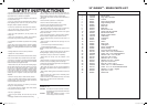
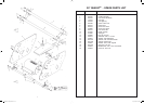
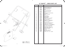
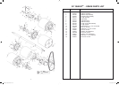
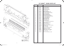
30” QUEEN
TM
- SPARE PARTS LIST
ITEM PART No. DESCRIPTION
1 302640 Grassboxassembly
2 164275 Rubber pad
3 164267 Pad mount
4 300847 Grassboxscreenassembly
5 303028 Heightcutsettingbar
6 509819 Decal- Scott Bonnar
7 3172749 Setscrew-1/4”x1”unc.HT.
8 A02044 Washer- 1/4” shakeproof
9 A02169 Setscrew-1/4”x1”unc.hex.
10 2531160 Wingnut-1/4”unc.
11 302658 Grassbox
3676 Queen 30 Reel Mower.indd 6 22/11/2005 4:27:35 PM