3 4
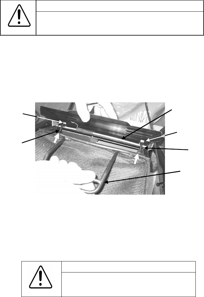
Removing the grass catcher– refer figure 3
• Move the throttle control lever to the stop position and wait till the blades have come to a
complete stop
• Raise the flap of the mower with one hand and with the other hand lift the grass catcher
up and away from the rear of the mower.
• Lower the rear flap against the rear of the mower.
The grass catcher should only be fitted or removed when
the engine is stopped. Never raise the rear flap when the
engine is running
WARNING
Figure 3. Grass catcher fitment
Hook
Hook
Grass catcher
handle
Flap rod
Slot in flap
Slot in flap
SETTING UP
With the aid of a second person remove the lawnmower from the carton and proceed to
assemble the handle bars to the mower.
Handle bar assembly- refer figure 1
• Fold the handle bars out straight, taking care not to
damage the throttle cable which is looped around the
engine for transit. Tighten the handle bar knobs.
• Position the throttle cable and throttle control to the right
hand side of the mower for assembly to the mower
Cuphead bolts
and washer
face hex nuts
Mower bracket
Lower handle bar
Figure 2. Handle bar assembly
OPERATION
Installing the grass catcher- refer figure 3
• Move the throttle control lever to the stop position and wait till the blades have come to a
complete stop
• Raise the rear flap of the mower with one hand and with the other hand raise and position
the grass catcher against the rear of the mower.
• Locate the two hooks on the front of the grass catcher frame into the slots on either side of
the rear flap and over the rear flap pivot rod.
Under normal usage the grass catcher material is subject to deterioration
and wear, and should be frequently checked for wear or damage.
Replace with a genuine Rover grass catcher if found to be damaged.
WARNING
Engine oil
Oil must be added before attempting to start the engine otherwise
damage to engine will occur.
Refer to the engine manufacturer owner’s manual
The 4 stroke engine fitted to the Rover lawnmower is shipped with no oil in the sump.
Engine fuel
Refer to the engine manufacturer owner’s manual
Use only fresh unleaded petrol in the lawnmower engine.
Figure 1. Handle bar knobs
• Align the lower handle bars against
the inner face of the mower brackets,
located at the rear of the mower base.
Insert the four cuphead bolts from the
outside through the mower brackets
first and into the lower handle bars,
and retain with the four washer face
hex nuts on the inside of the lower
handle bar and tighten.
Refer to figure 2
Handle bar knob


