


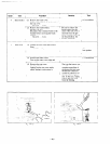
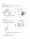
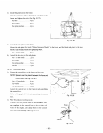
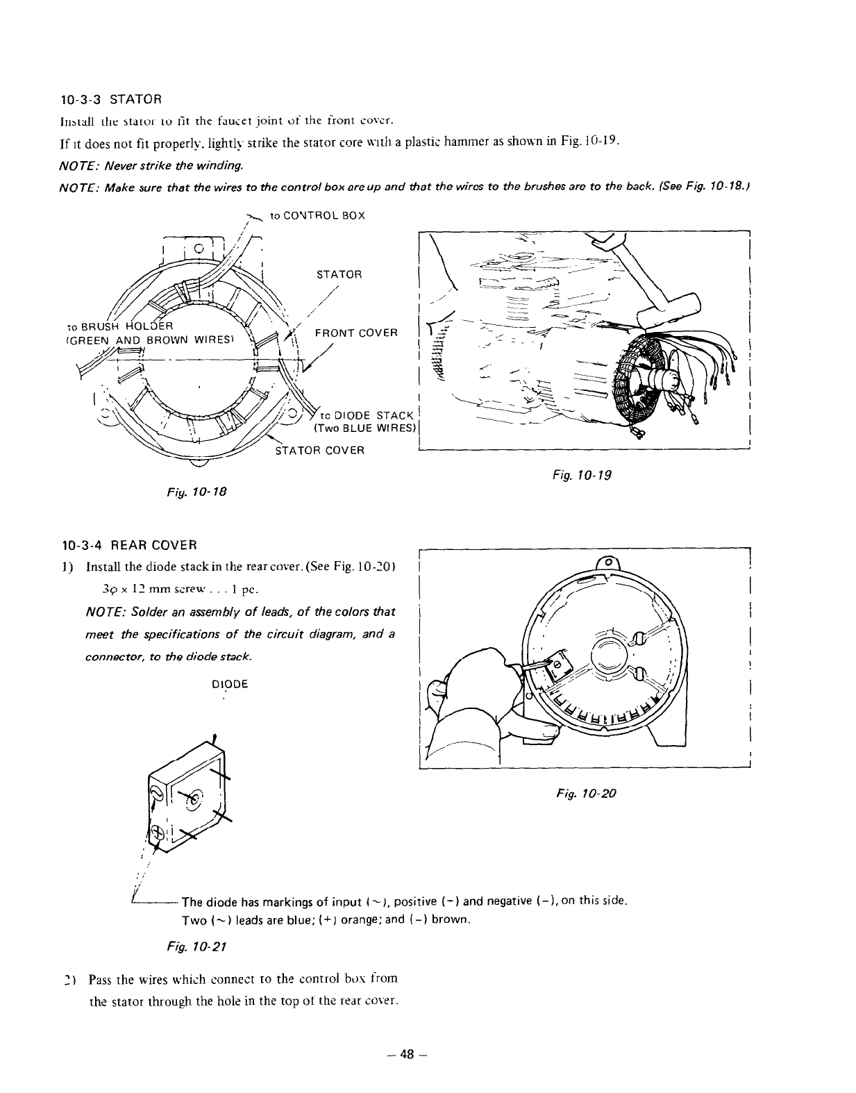
10-3-3 STATOR
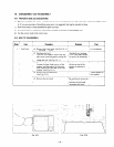
Install the stator to tit the faucet joint of the front cwer.
If it does not fit properly. lightl>- strike the stator cnre \vltil a plasti,
_ hammer as shown in Fig. 1 O-19.
NOTE: Never strike the winding.
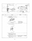
NOTE: Make sure that the wires to the control box areup and that the wires to the brushes are to the back. (See Fig. 70-78.)
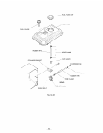
y., ta COYTROL BOX
STATOR
:cj BRUiti liOL%R
VER
I
STACY [
WIRES)1
I
Fig. IO-18
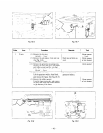
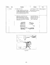
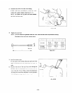
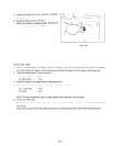
10-3-4 REAR COVER
1) Install the diode stackin the rearcover.(See Fig. 10-20)
39 x 12 mm screw. . . 1 pc.
NOTE: Solder an assembly of leads, of the colors that
meet the specifications of the circuit diagram, and a
connector, to the diode stack.
DIODE
I
Fig. lo-19
Fig. IO-20
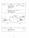
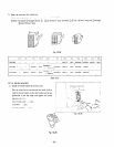
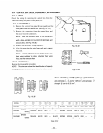
L The diode has markings of input ( -J, positive (-) and negative (-j, on this side.
Two (5) leads are blue; (+ J orange; and (-j brown.
Fig. 70-21
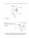
3) Pass the wires Lvhich connect to the control b~,x from
the stator through the hole in the top of the rear co~r.
-
48 -