


COMBAT
®
UHA UNIT HEATER INSTALLATION OPERATION AND SERVICE MANUAL
14
SECTION 8: GAS PIPING
It is important that the gas supply pipe and the
electrical connections do not support any of the
heater’s weight.
A gas meter is connected to the service pipe by the
gas supply company. An existing meter should be
checked, preferably by the company, to ensure that
the meter is adequate for the rate of gas supply
required.
Installation pipes must be fitted in accordance with
local and national codes. Pipes of smaller size than
the heater inlet gas connection should not be used.
8.1 Connections
Connect the heater to the gas supply ensuring that
the final connections are as follows:
• Gas supply pipe work is run in medium or heavy
gauge tubing in compliance with local and
national codes.
• Meter and service must be large enough to
handle all the burners being installed plus any
other connected load. The gas pipe which feeds
the system must be large enough to supply the
required gas with a maximum pressure drop of
1/2" w.c. When gas piping is not included in the
layout drawing, contact the local gas supplier.
• An isolating valve and union connection should
be used and fitted into the supply adjacent to the
heater.
• A minimum 1/8" NPT plugged tapping
accessible for test connection must be installed
immediately upstream of the gas supply
connection to the heater.
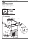
• For suspended heaters, an approved metal
flexible connection between the isolating valve
and the heater may be used. To reduce
pressure loss, use one pipe size larger than
the heater gas connection.
IMPORTANT - The complete installation must be
purged and tested for gas soundness in accordance
with local and national codes.
• Do not high pressure (in excess of 1/2 psi
[14" w.c.]) test the gas piping with the burner
connected. Close manual shut-off valve
during any pressure testing equal to or less
than 1/2 psi (14" w.c.). Failure to follow these
instructions can result in property damage.
Check the pipe and tubing ends for leaks before
placing heating equipment into service. When
checking for gas leaks, use a soap and water
solution; never use an open flame.
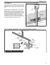
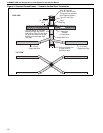
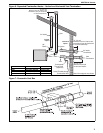
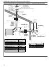
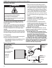
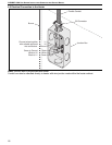
Figure 9: Gas Connection
WARNING
Fire Hazard
Connect gas supply according to Figure 9.
Gas can leak if not installed properly.
Failure to follow these instructions can result in death,
injury or property damage.
Fire Hazard
Connect gas supply according to Figure 9.
Gas can leak if not installed properly.
Failure to follow these instructions can result in death,
injury or porperty damage.
Gas Shut-off Valve
Drip Leg
Cap
Union
Connection
Option B:
Medium or Heavy
Gauge Pipe
Gas Connector
Option A:
Stainless Steel
Flex Gas
Connector
Do not bend flexible
gas connector
sharply.
• Hold gas nipple
securely with pipe
wrench when
attaching the flex gas
connector.
• Do not twist flexible
gas connector.
• Ensure all
joints are
gas tight.