


UHA LOW PROFILE UNIT HEATER INSTALLATION OPERATION AND SERVICE MANUAL
16
• In the event that the requirements of this
subdivision can not be met at the time of
completion of installation, the owner shall have a
period of thirty (30) days to comply with the
above requirements; provided, however, that
during said thirty (30) day period, a battery
operated carbon monoxide detector with an
alarm shall be installed.
Approved Carbon Monoxide Detectors: Each carbon
monoxide detector as required in accordance with
the above provisions shall comply with NFPA 720
and be ANSI/UL 2034 listed and IAS certified.
Signage: A metal or plastic identification plate shall
be permanently mounted to the exterior of the
building at a minimum height of eight (8) feet above
grade directly in line with the exhaust vent terminal
for the horizontally vented gas fueled heating
appliance or equipment. The sign shall read, in print
size no less than one-half (1/2) inch in size, “GAS
VENT DIRECTLY BELOW. KEEP CLEAR OF ALL
OBSTRUCTIONS”.
Inspection: The state or local gas inspector of the
side wall horizontally vented gas fueled equipment
shall not approve the installation unless, upon
inspection, the inspector observes carbon monoxide
detectors and signage installed in accordance with
the provisions of 248 CMR 5.08(2)(a)1 through 4.
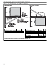
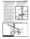
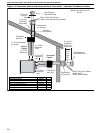
6.6 Vertical Venting
Vertically vented heaters can be common vented
(up to four heaters).
For vent lengths greater than 5' (1.5 m),
condensation will form. Insulation is recommended
and condensation drains may be desired. Venting
through the top of the heater cabinet is not
recommended if vent lengths are longer than 10'
(3 m). In this case, vent from the rear of the heater
cabinet then run the vent vertically and use a
condensate drain at the bottom of the vertical vent.
Vent pipe must be sloped 1/4'' (.6 cm) for every 1' (.3
m).
For 4'' (10 cm), an approved vent cap
(P/N 90502102) must be used.
For 6'' (15 cm) common vent, an approved vent cap
(P/N 90502103) must be used.
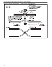
For common vertical venting of more than two
heaters, See Page 18, Figure 11.
A vent shall not extend less than 2' (.6m) above the
highest point where it passes through a flat roof of a
building.
6.7 Length Requirements
If using vent lengths greater than 5' (1.5 m),
condensation will form in the vent pipe. Insulation
and additional sealing measures (high temperature
silicone at all seams) are required.
The entire vent should be insulated with foil faced
fiberglass insulation (1/2" thick, 1-1/2# density
minimum).
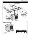
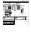
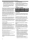
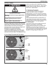
6.7.1 Maximum Vent Lengths
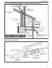
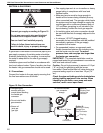
6.8 Vent Material
Vent material may be single wall 26 ga. (minimum)
galvanized steel or equal thickness stainless steel.
Completely seal all joints, refer to Page 14, Section
6.3.
If penetrating a combustible wall or roof, a listed
thimble with 2" (5 cm) clearance must be used.
Where local codes permit, a single section of type
B-1 vent material may be used at the roof or wall
penetration instead of a thimble. Ensure vent
manufacturer's clearance from vent material is
maintained. Seal annular space of the type B-1 vent
as well as all joints in the remaining vent.
6.9 Replacing an Existing Heater in a Venting
System
When replacing an existing heater in a venting
system, the venting system may not be properly
sized to vent the new heater. The following steps
must be followed with each appliance connected to
the venting system placed in operation, while any
other appliances connected to the venting system
are not in operation.
1. Seal any unused openings in the venting
system.
2. Inspect the venting system for proper size and
horizontal pitch, as required by the NFPA 54/
ANSI Z223.1 - latest revision, National Fuel
Gas Code (US) or Standard CSA B149.1
Natural Gas and Propane Installation Code
(Canada) and these instructions. Determine
that there is no blockage or restriction, leakage,
corrosion and other deficiencies which could
cause an unsafe condition.
3. Close all building doors and windows and all
doors between the space in which the
appliance(s) connected to the venting system
Model UHA[X][S]
30 - 60
Model UHA[X][S]
75 - 125
Number of Elbows
25 ft (7.6 m) 40 ft (12.2 m) 1
20 ft (6.1 m) 35 ft (10.7 m) 2
15 ft (4.6 m) 30 ft (9.1 m) 3
10 ft (3.0 m) 25 ft (7.6 m) 4
5 ft (1.5 m) 20 ft (6.1 m) 5