


16
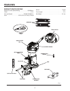
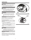
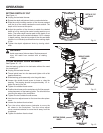
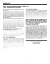
SETTING DEPTH OF CUT
See Figure 11.
n Unplug the laminate trimmer.
n Rotate the depth adjustment knob counterclockwise.
n Slide the motor housing section of the trimmer upward
until the tip of the cutter reaches the work surface. The
depth of cut is zero at this point.
n Adjust the position of the trimmer to obtain the desired
depth of cut by moving the motor housing section up or
down. The cutter depth can be read on the depth of cut
scale. Each mark on the scale indicates a 1/16 in. change
in depth setting. Use the top edge of the die-cast base
(depth of cut indicator) as reference when setting depth
of cut.
n Tighten the depth adjustment knob by turning clock-
wise.
WARNING:
Avoid open area of trimmer base. Serious personal
injury will result from contact with a rotating
cutter.
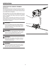
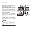
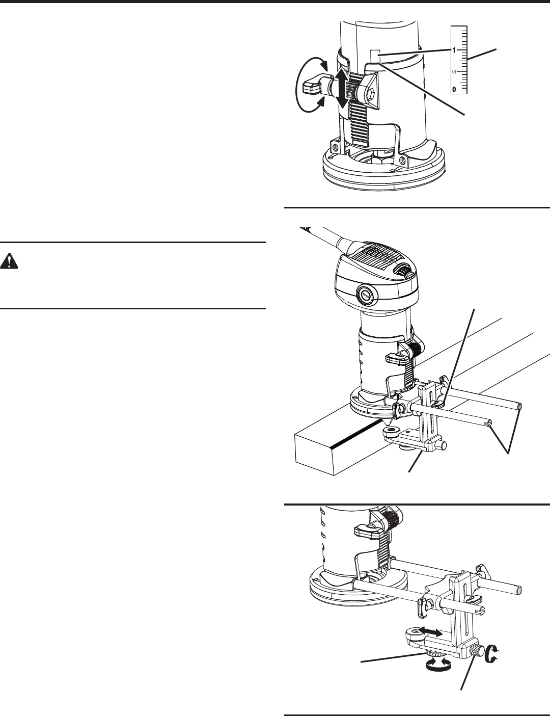
TO USE BEARING GUIDE ASSEMBLY
See Figures 12 - 13.
���Use the bearing guide to trim laminates without the need
for a bearing bit.
n Unplug the laminate trimmer.
n Thread guide bars into the base and tighten with a flat
head screwdriver.
n Slide bearing guide assembly onto the guide bars.
n Loosen the middle thumb screw to lower or raise the
bearing. The bearing should be approximately 1/2 in.
below the end of the bit.
n Tighten the middle thumb screw.
n Position the trimmer on the workpiece to find the approxi-
mate placement of the bearing guide. The bit should be
touching the edge of the workpiece.
n Tighten the two outside thumb screws.
n Use the micro adjust screw to fine tune the cutter place-
ment.
n Loosen the bottom thumb wheel.
n Turn the micro adjust screw clockwise to move the
bit closer to the workpiece. Turn the micro adjust
screw counterclockwise to move the bit away from the
workpiece.
n Tighten the bottom thumb wheel.
OPERATION
Fig. 11
Fig. 12
Fig. 13
BEARING GUIDE
ASSEMBLY
MIDDLE THUMB
SCREW
GUIDE BARS
DEPTH OF CUT
SCALE
BOTTOM THUMB
WHEEL
MICRO ADJUST
SCREW
DEPTH OF CUT
INDICATOR