ASSEMBLY
SE8A 01/11 Assembly Section 3-4
© 2011 Alamo Group Inc.
ASSEMBLY
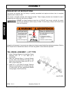
The Components of these machines are quite heavy. Block all components up securely
before working under or putting extremities under such parts.
TONGUE
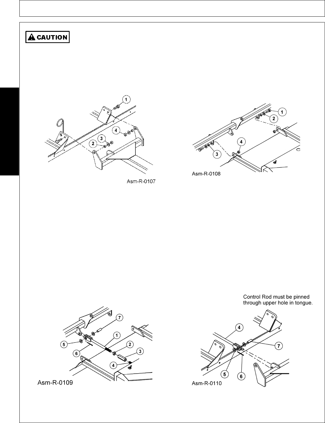
Insert 1-1/8" OD bushing(2) in tongue lug holes. Align bushings between the upright lugs on front of Main
Frame. Use 7/8" x 2-1/2" bolts (1), flatwasher (3), and locknut (4) to secure. FIGURE Asm-R-0107
AXLE ASSEMBLY
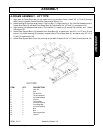
Attach the Rear Axle to the lugs on the rear of the Main Frame using 3/4" x 2" bolts (1), bushings 1" OD x 3/4"
(3), flatwashers (2), and locknuts (4). FIGURE Asm-R-0108.
CONTROL RODS
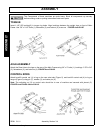
Attach level-lift control rod (1) to lug on the rear axle tube (Figure 5), and level-lift control rod (4) to lug on
tongue (Figure 6) using pin (7), washer (5), and cotter pin (6).
Note: The adjusting nut (3) on control rods should be to rear of machine and secured with jamnut (2).
FIGURE Asm-R-0109 & Asm-R-0110.


