


3
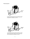
III. Water Connections
The heat pump inlet and outlet connections are NOT interchangeable.
They must be connected as instructed below.
1. Connect the heat pump in the return water line between the pool filter and the pool. See
page 10, Plumbing Diagrams.
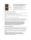
2. Connect the filter outlet to the fitting marked
WATER IN at the bottom front of the unit.
3. Connect the fitting marked
WATER OUT to the return piping to the pool. Unit inlet/outlet
connection fittings are 2-inch PVC slip couplers.
Water connections from the heat pump to the main return line can be PVC pipe or flexible pipe
approved for the purpose and, in either case, should be at least equal in size to the main pool
circulation piping.
4. In cold weather (freeze zone) areas, shutoff valves (ball or gate type) must be installed at the
heat pump inlet and outlet to facilitate service and cold weather drain-down.
5. When the water connections are complete, operate the pool pump and check the system for
leaks.
Automatic chemical feeders should not be installed upstream of the heat pump. Improper
installation of erosion-type automatic chemical feeders can result in serious damage to, or
premature failure of, the heat pump. A flow check valve and/or a Hartford loop will be required.
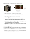
IV. Controls and Indicator Lamps
Your heat pump incorporates safety controls and indicators to ensure its safe, reliable operation.
Water Pressure Switch: Prevents operation when the pump is OFF. The unit requires 5 psi
minimum pressure.
Water Temperature Control: Pool/spa water temperature is controlled by the heat pump
thermostat on the unit control panel, which contains a switch and 2 thermostats, one for setting a
heat spa temperature and the other for a swimming pool temperature. The switch can operate an
optional external control system, or can switch between thermostats for pool or spa.
NOTE: The heat pump will not run when the Remote position is selected
and there is no remote control system attached.
Defrost Switch: Prevents heat pump operation if ambient air temperature falls below a
predetermined safe minimum (approximately 42° F).
Delay Timer: Prevents compressor from short cycling, which could damage or destroy the
hermetic motor/compressor. Upon water temperature control satisfaction, or other control circuit
interruption, this solid state device will prevent compressor restart for approximately 5 minutes.
Upon power failure or interruption, a 6 to 8 minute delay will also be initiated.
Refrigerant Low Pressure Control: Stops the compressor if refrigerant suction (low side)
pressure falls too low as a result of a malfunction or loss of charge.
CAUTION