


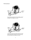
2
• Each side of the unit must be located at least 1 ft from walls, pipes, or other obstructions for
unrestricted air intake and service access.
Do not install the unit within 3 ft of fossil fuel burning heaters. Air intake
along the sides of this heat pump could disturb the combustion process
of the unit, and could cause damage or personal injury.
• Mount the unit on a level, sturdy base, preferably a concrete slab or blocks. The size of the
base should be not less than 3 ft by 3 ft.
• Completely isolate the base from the building foundation or wall to prevent sound or
vibration transmission into the building. For this purpose, 4 black rubber sound isolation
pads are included with the unit. These pads must be installed under the corners of the
unit to reduce vibration and sound transmission to the base.
• If the unit is installed in an area known for water accumulation during periods of heavy
rainfall, its supporting base must be high enough to keep it completely free of standing water
at all times.
II. Electrical Connections
The table below lists the typical electrical power requirements for your heat pump.
Refer to the unit rating plate below the control panel for precise power requirement for each unit,
and for ampacity and over-current protection requirements. All wiring must be in accordance with
the National Electrical Code, NFPA No. 70, latest edition, and all applicable state and local codes.
NOTE: Refer to the National Electrical Code, Article 680, for general requirements
for swimming pools and equipment, and to Article 440 for special considerations
necessary for circuits supplying hermetic refrigeration motor/compressors.
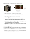
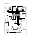
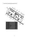
The power supply connections to the unit are located behind the control panel. Remove the
control panel to expose the electrical controls. Line voltage connections are made at the line
voltage terminals of the compressor contactor. Refer to the Heat Pump Schematic (page 11) and
the Control Panel Assembly Replacement Parts List (page 12).
Conduit entrance to the unit is through a hole below the control panel.
NOTE: Make certain all electrical connections to unit terminals are secure.
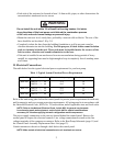
Table 1: Typical System Electrical Power Requirements
Model VIN - Phase - Hz Min. circuit Ampacity (A) Max. breaker size (A)
RHP 100 208/230 - 1 - 60
208/230 - 3 - 60
31.4
20.5
50
30
RHP 115 208/230 - 1 - 60
208/230 - 3 - 60
40.4
27.5
60
40
RHP 160 208/230 - 1 - 60 46.2 60
WARNING