


12
Raypak recommends the installation of an air bleed
vent at a suitable location (usually the highest point in
the plumbing) to remove air from the piping system.
These units should be available at your local whole-
sale supplier. Raypak does not provide this item.
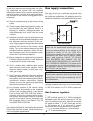
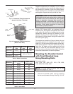
Models 1287 through 4001 are equipped with an
external pump and bypass arrangement that blends
outlet water with the inlet to increase the inlet water
temperature, thereby reducing the likelihood of con-
densation forming on the heat exchanger. The pump
also serves to circulate water through the heater from
the main system piping.
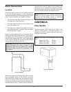
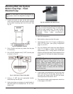
To complete the installation of the pool heater, the pool
thermostat needs to be installed in the main return
water line. This will ensure that the heater will be ener-
gized at the right time. If the main water line is too far
away from the heater and the capillary bulb will not
reach it, locate the pool thermostat adjacent to the
main line and run wires back to the heater. Follow the
instructions listed below to install the poolstat.
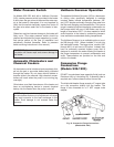
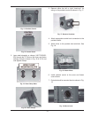
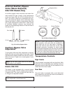
Mounting the Poolstat Control
with Front-Mounted Loop
Using Mounting Slots
For heater models:
1287, 1336, 1414, 1468, 1571, 1631, 1758, 1826,
2100, 2500, 3001, 3500, 4001.
1. Remove the poolstat control cover by removing
the two cover screws at the top. See Fig. 13 & 14.
C
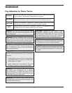
AUTION: Power to the heater should be
interlocked with the main system pump to make sure
the heater does not fire without the main system
pump in operation. Improper flow control can
damage the heater. Uncontrolled flow (too high) or
restricted flow (too low) can seriously affect heater
operation. Follow these instructions to make sure
your heater is properly installed.
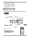
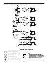
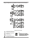
NOTE: For more detail on piping, refer to the
diagrams on pages 15, 16 & 17.
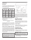
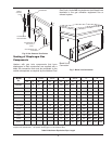
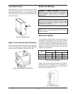
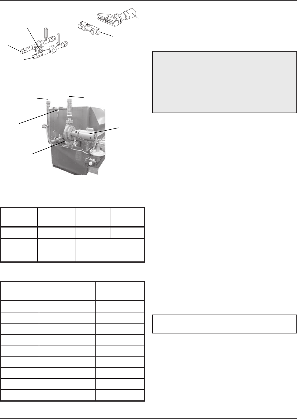
Inlet/Outlet
Header
2-1/2" Inlet
2-1/2" Outlet
1-1/2" Slip Ball Valve
Pum
p
F
ig. 11: Companion Flange Connections
(Models 1287/1336–1758/1826)
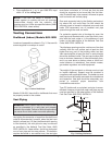
2" Slip
Ball Valve
3"
Outlet
3"
Inlet
2 H.P. Pump
I
nlet/Outlet
Header
Fig. 12: Companion Flange Connections
(Models 2100–4001)
Model No.
Connection
Size
Minimum
gpm
Maximum
gpm
926–1223 2” FPT 60 120
1287–1826 2-1/2” FPT
Refer to Table D
2100–4001 3” FPT
Table C: Water Connections
Model No.
Loop* Flow Rates
(gpm)
Heater Flow
Rates (gpm)
1287/1336 30–50 85
1414/1468 35–55 85
1571/1631 40–65 85
1758/1826 45–70 85
2100 50–80 180
2500 60–95 180
3001 75–115 180
3500 90–135 180
4001 100–150 180
Table D: Flow Rates
*Loop is secondary piping to heater from main system.