


14
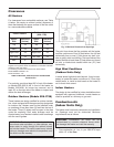
To adjust the temperature:
1. Both isolation valves must be fully open.
2. Adjust Bypass Valve "A" 1/2 open and Balancing
Valve "B" fully open. (See piping configuration
page 15, 16 & 17)
3. Fire your Raypak pool heater and adjust Bypass
Valve "A" to obtain a heater inlet temperature
approximately 105°F. Turning Valve A in the open
direction will raise the heater inlet temperature and
closing Valve "A" will lower the heater inlet temper-
ature.
4. If the heater inlet temperature remains less than
100°F and Valve "A" is fully open, leave Valve "A"
fully open and throttle Valve "B" until the heater
inlet temperature rises above 105°F.
5. The resultant heater outlet temperature should be
in the range of 120-130°F.
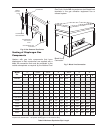
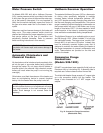
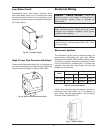
Fig. 22: Installation with Weld O Lets
NOTE: The drawings and instructions above show
only one of several acceptable ways of installing the
dry well into main system loop. The use of saddle
clamps and “Weld O Lets” (shown in Fig. 22) are
acceptable. Follow clamp manufacturer’s
instructions.
CAUTION: The inlet water temperature must be
kept above 105°F. Changes in system flow or valve
position may require re-adjustment of the flow
settings. Check the heater bypass settings after
making adjustments. Failure to maintain an inlet
temperature above 105°F may result in damage to
the heater. Failure to comply with this instruction
voids the warranty.
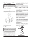
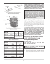
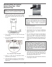
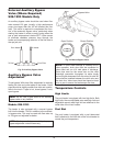
Mounting Well into System
Return Loop Pipe - Front-
Mounted Loop
1. Locate and mark an area on the main system
return loop pipe where the well is always exposed
to the water circulating back from the pool. See
Fig. 20.
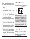
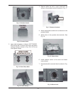
2. Shut off water and drain any water from the pipe
as necessary.
3. Drill a 23/32" diameter hole (½” NPT) into the pipe
as shown in Fig. 21.
4. Using a ½” NPT tap and appropriate handle,
thread the tap into the pipe.
5. Apply pipe dope as necessary to male threads of
well and insert into threaded hole. Do not over-
tighten well.
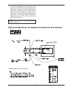
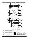
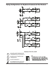
NOTE: For more detail on piping configurations for
large systems, refer to the diagrams on pages 15, 16
& 17.
HEATER
Fig. 20: Installation Location
Fig. 21: Drill Hole in Pipe for Dry Well