


6
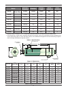
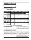
Sample Installation Diagram
NOTE:
-Damage to the Indirect Pool Heater due to improper water chemistry is not covered under the warranty
- Chlorine feeder must be installed after (downstream of) the Indirect Pool Heater and be installed with an
anti-siphoning valve to prevent chlorine from backing up into the Indirect Pool Heater.
- This is only a conceptual drawing. A qualified installer must determine whether this system setup
will work in each application. Installer must also ensure compliance with code requirements.
1.
2.
Indirect Pool Heater
3.
4.
5.
6.
Gate valve
7.
Check valve
8.
9
.
10.
Flow switch
11.
Thermometer
Drain valve
Filter
Pool/Spa Pump
Bypass valve
POOL WATER FLOW
POOL WATER FLOW
BOILER WATER FLOW
BOILER WATER FLOW
6
Thermostat or Aquastat
3
1
4
6
2
2
9
8
5
7
10
2
2
11
11
Union
TO BOILER CONTROL
12.
Boiler Pump
11
11
3
12
On the pool side the flow may be variable either due to
variable speed pumps or changes in the pressure drop
through the filtration system. These variances can be
accommodated by installing a 2lb spring loaded check
valve in the bypass line along with a manual valve (see
Figure 2 for details).
On model sizes 045 to 495, the check valve will con-
trol bypass flow by directing all flow through the
exchanger under low flow conditions, and avoiding
excessive flow through the heat exchanger under high
flow conditions. On 995 models the 2lb check valve
does not provide enough resistance to direct adequate
flow through the heat exchanger, and must be aug-
mented by using the manual valve to throttle flow to
provide approximately 6 to 15 ft of head across the
995 exchanger.
Controls
The Indirect Pool Heater must be installed with tem-
perature and flow controls to protect the heat
exchanger and control water temperature supplied to
the pool or spa. The return from the pool/spa must be
controlled at the inlet to the Indirect Pool Heater by a
thermostat set to the desired temperature for the
pool/spa, with the maximum recommended operating
temperature of 104°F. A second temperature control
must be installed in the outlet piping of the Indirect
Pool Heater to limit pool/spa supply temperatures to
140°F maximum. In addition to the temperature con-
trols, a flow switch should be installed in the pool/spa
supply line to prove adequate flow through the heat
exchanger. All three of these controls must be satis-
fied to provide a call for heat to the heat source.
Chlorine feeders or salt water
generators
The chlorine feeder or salt water generator (with CR24
exchangers only) must be installed after (downstream
of) the Indirect Pool Heater and be installed with an
anti-siphoning valve to prevent chlorine from backing
up into the Indirect Pool Heater. During periods of high
or fluctuating chlorine levels the Indirect Pool Heater
must be isolated from the system by closing the isola-
tion valves, protecting the unit from chemical damage.
CAUTION: Operating control, high limit and flow
switch are NOT part of the Indirect Pool Heater.
These items must be supplied separately.