


23
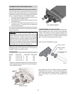
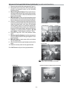
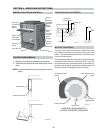
1. Remove right and left side access panels (Figure 1).
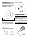
2. Disconnect wires at high limit, AGS (automatic gas
shutoff), and pressure switch on the inlet/outlet
header(Figure 2).
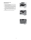
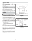
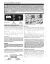
3. Electronic Ignition Heaters: Remove the thermo-
stat temperature sensor by loosening the compres-
sion fitting nut (Figure 3). Reroute the sensor to the
left side of the heater.
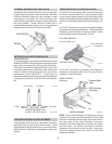
4. Millivolt Heaters: Remove the temperature sensor
bulb and retainer clip from the sensor well (Figure 4).
Reroute the sensor bulb to the left side of the heater.
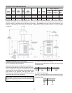
5. Remove (12) bolts holding the inlet/outlet and return
headers to the tube sheets. Clean off tube sheet area
where the gasket seats. Also clean off the header
and the gasket. Apply a non-petroleum based lubri-
cant to the gasket such as Aqua Lube. Reattach the
headers to the opposite sides, making sure they are
installed in an upright position (Figure 5). Do not
over tighten. Torque should not exceed 7 ft/lbs.
6. Reconnect high limit, AGS, and pressure switch
wires.
7. Electronic Ignition Heaters: Insert the temperature
sensor in the compression fitting and tighten 1/2 turn
past hand tight.
8. Millivolt Heaters: Insert sensor bulb and retainer
clip into sensor well.
9. Allow for water flow through the heater and check for
leaks.
10. Reattach access panels to the opposite sides.
For ASME Models call your factory representative.
Fig. #3
JACO FITTING
NOTE:Tighten almost flush
(1/32" to 1/8") to the header to avoid leaks.
Fig. #2
PRESS SWITCH AGS HI-LIMIT
Fig. #4
BULB & CLIP
Fig. #5
REINSTALLED IN/OUT HEADER ON OPPOSITE SIDE.
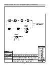
RP2100 HEAT EXCHANGER REVERSAL PROCEDURE (POLYMER HEADER MODELS)
Fig. #1
ACCESS PANEL